V1
1 185vdc
2
3 2.2vdc
6 255vdc
7
8 2.2vcd
V2
1 308vdc
2
3 1.78vdc
6 351vdc
7 309vdc
8 309vdc
V3
1 280vdc
2 30.1vdc
3 49vdc
6 251vdc
7 31.3vdc
8 49vdc
V4
1
3 456vdc
4 458vdc
5 -57vdc
6 450vdc
8
V5
1
3 459vdc
4 459vdc
5 -57vdc
6 440vdc
8
Issue With Bassman 5F6A Build
Moderators: pompeiisneaks, Colossal
Re: Issue With Bassman 5F6A Build
I went to pick up some Switchcraft 12A jacks and of course the guy only had 3 in stock. Can I temporarily terminate the bright channel mix resistors to ground with 1M resistors so I can proceed with wiring the normal channels?
Peace,
Mark
Peace,
Mark
-
JazzGuitarGimp

- Posts: 2357
- Joined: Mon Jul 23, 2012 4:54 pm
- Location: Northern CA
Re: Issue With Bassman 5F6A Build
Looks like you have an issue at V2b. Check your cathode wiring as it looks like the cathode is not connected.
Lou Rossi Designs
Printed Circuit Design & Layout,
and Schematic Capture
Printed Circuit Design & Layout,
and Schematic Capture
Re: Issue With Bassman 5F6A Build
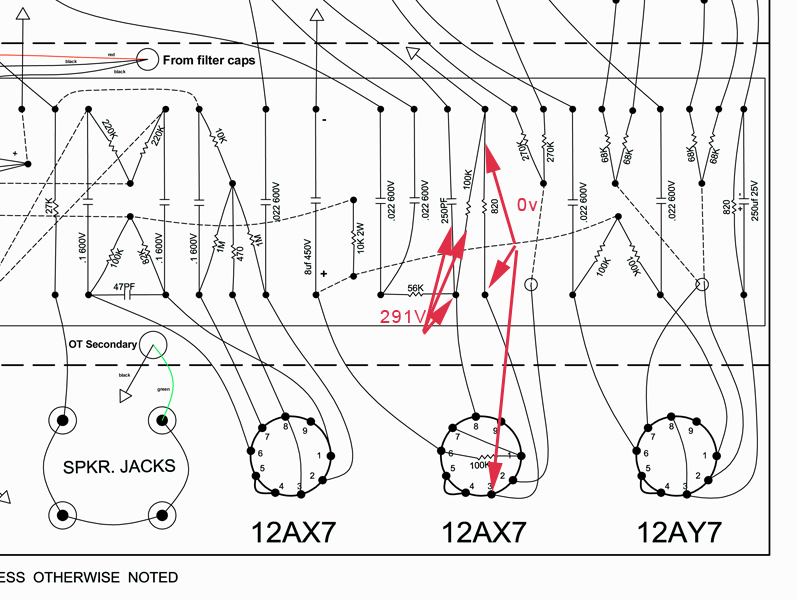
Just checked it. Still 0v. The 820 and 100K meter fine. I have 819 ohms from the cathode to ground. That tells me the R and solder joints are likely good. The ground side of both Rs are at 0v also.JazzGuitarGimp wrote:Looks like you have an issue at V2b. Check your cathode wiring as it looks like the cathode is not connected.
Bad tube perhaps? Bad ground?
[img:800:600]http://www.crenshawweb.com/bassman/v2b_cathode.jpg[/img]
Mark
-
JazzGuitarGimp
- Posts: 2357
- Joined: Mon Jul 23, 2012 4:54 pm
- Location: Northern CA
Re: Issue With Bassman 5F6A Build
I am referring to the cathode at pin 8 (sorry I wasn't more specific). You've got 309v there, which implies a problem with its groind reference.
Lou Rossi Designs
Printed Circuit Design & Layout,
and Schematic Capture
Printed Circuit Design & Layout,
and Schematic Capture
-
JazzGuitarGimp
- Posts: 2357
- Joined: Mon Jul 23, 2012 4:54 pm
- Location: Northern CA
Re: Issue With Bassman 5F6A Build
Oops, now that I've looked at the schematic, I see V2B is wired as a CF. i take back everthing I said. Can I get a do-over, please? Carry on....
Lou Rossi Designs
Printed Circuit Design & Layout,
and Schematic Capture
Printed Circuit Design & Layout,
and Schematic Capture
-
martin manning

- Posts: 14308
- Joined: Sun Jul 06, 2008 12:43 am
- Location: 39°06' N 84°30' W
Re: Issue With Bassman 5F6A Build
Yes, you can ground the Bright channel's 68k's and get it out of the picture for now.
I would ground the reservoir (2x 22uF first filter) with the PT CT, and ground the other filters to the buss at the PT end.
V1 looks ok, but the two triodes are not very well matched, or possibly there is a difference in the load resistance due to a bad joint (assuming both plate resistors are 100k)
V2 looks odd. The B+ looks good (reading pin 6 as connected to B+), but the plate voltage on the other triode (pin 1) is 100V too high. In the diagram above you show 0V on the cathode at pin 3 but 1.78V in your table. If it is 0V, I suspect that there is a bad joint between pin 3 and ground. Measure resistance to ground from the cathode pin and both sides of the 820R on its leads. Running 300V on the cathode is not good for the heater-cathode insulation!
V3 looks good. You can't measure the grid voltage (pins 2 and 7) directly because your meter is providing a new ground reference. Measure at the junction of the four resistors (1M 1M 470 10k) to get a better idea of the grid voltage.
V4 and V5 pins 3 and 4 look reasonable, but in both cases pin 6 is lower than pin 4, which would say that the screen current is flowing the wrong way. I don't know what to make of that.
You'll have to find a way to set the bias at some point. The easiest and safest way is to ground the power tube cathodes through 1-ohm, 1% resistors so that the measured voltage on the cathodes in mV is numerically equal to the current in mA. I see you have the power tube cathodes grounded directly to the buss at this point. An alternative is to measure the DC resistance of the OT primary on each side and use that resistance to calculate the current for each power tube. This is true plate current, but more of a PITA to do, and you are probing points that are at high voltage.
Re: Issue With Bassman 5F6A Build
JazzGuitarGimp wrote:Oops, now that I've looked at the schematic, I see V2B is wired as a CF. i take back everthing I said. Can I get a do-over, please? Carry on....
Re: Issue With Bassman 5F6A Build
Thanks.martin manning wrote:Yes, you can ground the Bright channel's 68k's and get it out of the picture for now.
Will do.I would ground the reservoir (2x 22uF first filter) with the PT CT, and ground the other filters to the buss at the PT end.
They're both 100K. I'll try a different tube. Man, if there's a bad joint on this board, I'm giving up. I just don't know how I could have been more careful with soldering this time. I moved up to a 25W iron and I metered everything, every step of the way for resistence and continuity.V1 looks ok, but the two triodes are not very well matched, or possibly there is a difference in the load resistance due to a bad joint (assuming both plate resistors are 100k)
The B+ was still coming up as I was checking the second time. When I measured for the table, the amp had been idling for 15 mins. I checked pin 3 to ground last night and got 819-ohms.V2 looks odd. The B+ looks good (reading pin 6 as connected to B+), but the plate voltage on the other triode (pin 1) is 100V too high. In the diagram above you show 0V on the cathode at pin 3 but 1.78V in your table. If it is 0V, I suspect that there is a bad joint between pin 3 and ground. Measure resistance to ground from the cathode pin and both sides of the 820R on its leads. Running 300V on the cathode is not good for the heater-cathode insulation!
I think I checked the resistance there and it was in the 14K range. Will check the voltage this evening.V3 looks good. You can't measure the grid voltage (pins 2 and 7) directly because your meter is providing a new ground reference. Measure at the junction of the four resistors (1M 1M 470 10k) to get a better idea of the grid voltage.
If you don't know, I haven't a clue.V4 and V5 pins 3 and 4 look reasonable, but in both cases pin 6 is lower than pin 4, which would say that the screen current is flowing the wrong way. I don't know what to make of that.
I have 1-ohm 5W resistors and 3 pin jacks in my Mouser order that's arriving today. I figured with the variable resistor in the circuit, test points would be easiest to check while adjusting the pot.You'll have to find a way to set the bias at some point. The easiest and safest way is to ground the power tube cathodes through 1-ohm, 1% resistors so that the measured voltage on the cathodes in mV is numerically equal to the current in mA. I see you have the power tube cathodes grounded directly to the buss at this point. An alternative is to measure the DC resistance of the OT primary on each side and use that resistance to calculate the current for each power tube. This is true plate current, but more of a PITA to do, and you are probing points that are at high voltage.
Peace,
Mark
Re: Issue With Bassman 5F6A Build
So, in your overall opinion, am I making progress? It's starting to feel like the very definition of insantity.
If I can't get any sound out of it after grounding the bright channels and adding the 12A jacks on the normal channel, I'm either going to take it to a tech or use it for target practice.
Peace,
Mark
If I can't get any sound out of it after grounding the bright channels and adding the 12A jacks on the normal channel, I'm either going to take it to a tech or use it for target practice.
Peace,
Mark
-
Reeltarded

- Posts: 10189
- Joined: Sat Feb 14, 2009 4:38 am
- Location: GA USA
Re: Issue With Bassman 5F6A Build
Target practice might preclude using the parts again.
It 'looks' much better than before. It looks really nice. It looks like you took your time. If it doesn't work we will all be kind of pissed off at it with you.

It 'looks' much better than before. It looks really nice. It looks like you took your time. If it doesn't work we will all be kind of pissed off at it with you.
Signatures have a 255 character limit that I could abuse, but I am not Cecil B. DeMille.
-
vibratoking
- Posts: 2640
- Joined: Tue Nov 10, 2009 9:55 pm
- Location: Colorado Springs, CO
Re: Issue With Bassman 5F6A Build
Nah, you can beat this thing with Martin's help.... I'm either going to take it to a tech or use it for target practice.
-
Reeltarded
- Posts: 10189
- Joined: Sat Feb 14, 2009 4:38 am
- Location: GA USA
Re: Issue With Bassman 5F6A Build
Or a holey braille... lol
Signatures have a 255 character limit that I could abuse, but I am not Cecil B. DeMille.
-
JazzGuitarGimp
- Posts: 2357
- Joined: Mon Jul 23, 2012 4:54 pm
- Location: Northern CA
Re: Issue With Bassman 5F6A Build
Guitarnut, is it possible you've got the connections to the plates (pin 3) and screens (pin 4) swapped? Your output transformer leads should connect to pin 3, and your screen supply (usually a 470-ish ohm resistor to the power supply second node) should connect to pin 4.martin manning wrote:V4 and V5 pins 3 and 4 look reasonable, but in both cases pin 6 is lower than pin 4, which would say that the screen current is flowing the wrong way. I don't know what to make of that.
Lou Rossi Designs
Printed Circuit Design & Layout,
and Schematic Capture
Printed Circuit Design & Layout,
and Schematic Capture
-
martin manning
- Posts: 14308
- Joined: Sun Jul 06, 2008 12:43 am
- Location: 39°06' N 84°30' W
Re: Issue With Bassman 5F6A Build
Vibratoking is right, you'll get there, and its pretty close.
The only thing that looks to be way out right now is the 1-2-3 triode in V2. You got ~820 ohms to ground, but do you see 1.78V or 0V at the cathode? The plate voltage is high so it is not at the right operating point. The other side (the 6-7-8 triode) should come into line once this is resolved.
The V1 triodes won't match exactly, and you have 10% tolerance resistors in there too.