
Hi all,
I have a '72 Ampeg B25 I am refurbing.
I want to put in a trim pot to allow for adjustable bias.
I know I can just put a trim pot in (say, 50k with a ~22k resistor in series) but I want to have a failsafe to prevent damage to the amp/7027s if the trim pot's wiper fails.
How do I go about doing this?
Schematic of amp in question.
Failsafe for bias trim pot on Ampeg B25
Moderators: pompeiisneaks, Colossal
-
Stevem
- Posts: 5144
- Joined: Fri Jan 24, 2014 3:01 pm
- Location: 1/3rd the way out one of the arms of the Milkyway.
Re: Failsafe for bias trim pot on Ampeg B25
I use a 20 turn cermette trimmer made by Vishay .
This type of trimmer will not go open like the connection in a regular resistance trace type pot can and leave the output stage with no bias voltage.
Get it in the value you need, but these need to be hard wired as you can see from my photo.
I silicon glue them to the chassis, or when I have the room I solder the whole little bias circuit onto a bread board.
The 20 turn range allows very precise adjustment of the voltage.
If you place a small dab of silicon glue to the screw head and the body it will add enough friction that the adjustment you make will not change.
You do not have the required permissions to view the files attached to this post.
When I die, I want to go like my Grandfather did, peacefully in his sleep.
Not screaming like the passengers in his car!
Cutting out a man's tongue does not mean he’s a liar, but it does show that you fear the truth he might speak about you!
Not screaming like the passengers in his car!
Cutting out a man's tongue does not mean he’s a liar, but it does show that you fear the truth he might speak about you!
-
martin manning

- Posts: 14308
- Joined: Sun Jul 06, 2008 12:43 am
- Location: 39°06' N 84°30' W
1 others liked this
Re: Failsafe for bias trim pot on Ampeg B25
I don't like that bias supply. It's switched on at the same time as the high voltage, and it will be slow to stabilize, meaning that an under-biased situation will exist for some seconds. I would be inclined to leave the standby in play permanently. That said, the circuit below will give fail-safe adjustable bias, and cut the stabilization time in half.
You do not have the required permissions to view the files attached to this post.
Re: Failsafe for bias trim pot on Ampeg B25
Hi Martin,martin manning wrote: ↑Mon Sep 11, 2023 4:43 pm I don't like that bias supply. It's switched on at the same time as the high voltage, and it will be slow to stabilize, meaning that an under-biased situation will exist for some seconds. I would be inclined to leave the standby in play permanently. That said, the circuit below will give fail-safe adjustable bias, and cut the stabilization time in half.
I see that the later B25B (schematic revised February 1974) has the bias circuit similar to your design. However, your design is situated between the diode anode and the bias resistor (R38) whereas the later Ampeg revision happens after R38. Because I am learning and am curious, I'd like to ask: what is the difference between this Ampeg revision and your design, if any?

-
martin manning
- Posts: 14308
- Joined: Sun Jul 06, 2008 12:43 am
- Location: 39°06' N 84°30' W
Re: Failsafe for bias trim pot on Ampeg B25
There are some subtle differences, but the 10u caps will bring the bias voltage down even faster, and the 10k between them will help keep the ripple voltage down. All you need to do is replace the 56k to ground after the diode with a 10k pot and a 47k in series, wired the same as in the circuit I posted. You may need to adjust the 47k to get the range dialed in for the tubes you are using.
Re: Failsafe for bias trim pot on Ampeg B25
Thank you Martin.martin manning wrote: ↑Mon Sep 11, 2023 6:24 pm All you need to do is replace the 56k to ground after the diode with a 10k pot and a 47k in series, wired the same as in the circuit I posted.
Any problem using a 25k pot with a 39k resistor? Or a 50k pot with a 22k resistor? I have no 10k pots, unfortunately...
-
martin manning
- Posts: 14308
- Joined: Sun Jul 06, 2008 12:43 am
- Location: 39°06' N 84°30' W
Re: Failsafe for bias trim pot on Ampeg B25
I picked 10k so that the whole sweep would be ~7 volts and therefore easy to adjust. If you use a bigger pot, it will be more sensitive.
Re: Failsafe for bias trim pot on Ampeg B25
Oh yeah, standby here is hot switching. So with a stressed rectifier and stressed output valves when it’s flipped, Ampeg managed to come up with a double turd sandwich of a standby switch 
https://www.justgiving.com/page/5-in-5-for-charlie This is my step son and his family. He is running 5 marathons in 5 days to support the research into STXBP1, the genetic condition my grandson Charlie has. Please consider supporting him!
Re: Failsafe for bias trim pot on Ampeg B25
So as Martin also said up above.
Best to just permanently keep the standby in the "on" position, then.
Re: Failsafe for bias trim pot on Ampeg B25
I didn’t notice that it’s been explicitly stated previously that the standby hot switches the (valve) rectifier? That’s why I posted
Yes, you could just leave the standby switch in its ‘amp operational’ mode. But it seems better to rearrange the switch for a more benign action, for when it passes on to its next owner / user.
https://www.justgiving.com/page/5-in-5-for-charlie This is my step son and his family. He is running 5 marathons in 5 days to support the research into STXBP1, the genetic condition my grandson Charlie has. Please consider supporting him!
Re: Failsafe for bias trim pot on Ampeg B25
OK, thanks for reminding me about that.
Referencing the Valve Wizard's advice.
Was thinking about implementing this ("Implementing a Standby Switch The Least Bad Way"):
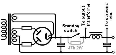
What do y'all think?
Re: Failsafe for bias trim pot on Ampeg B25
It looks good 

https://www.justgiving.com/page/5-in-5-for-charlie This is my step son and his family. He is running 5 marathons in 5 days to support the research into STXBP1, the genetic condition my grandson Charlie has. Please consider supporting him!
Re: Failsafe for bias trim pot on Ampeg B25
Thanks Pete!