New amp power up concerns

General discussion area for tube amps.

Moderators: pompeiisneaks, Colossal

User avatar
ViperDoc
Posts: 1247
Joined: Tue Dec 24, 2019 2:21 am
Location: Idaho

New amp power up concerns

Post by ViperDoc »

I finished wiring up an amp based off of a 100W Silver Jubilee. I built a light bulb limiter per the instructions on this website (thanks for that). I inserted a 40 W bulb, put in some fuses and turned it on. The bulb appears to be lit less than full brightness (I plugged the light bulb socket into the wall to compare and nearly blinded myself). I tested 430 VDC on the power supply can caps and 75 V on the bias supply tap. The power rail shows 430 VDC all the way down the line.

Concerns:

1) My socket heaters measure 2.4 VAC per side all the way down.
2) The can caps do not drain on power down. I have to drain them with a resistor stick.

Image

I haven’t finally dressed the OT wires because I want to swap them if I have to. Any recommendations? Thanks.
Just plug it in, man.
User avatar
xtian
Posts: 7263
Joined: Mon Apr 19, 2010 8:15 pm
Location: Chico, CA
Contact:

Re: New amp power up concerns

Post by xtian »

I don’t see any issues yet. Voltages will be a bit low with bulb limiter in place. And caps won’t drain unless your circuit has filter cap balance resistors. Keep going!
I build and repair tube amps. http://amps.monkeymatic.com
User avatar
ViperDoc
Posts: 1247
Joined: Tue Dec 24, 2019 2:21 am
Location: Idaho

Re: New amp power up concerns

Post by ViperDoc »

Here are some pictures. The power rail has closer to 440 VDC from the can caps all the way down to the preamp side when fully charged.

The PT has a center-tapped heater winding that I have to ground per the Marshall schematic. The fuses holders are taped in place until I get my panels shipped to me. The auxiliary transformer is for relay heaters and tests well at 3.1 VAC per side.

Image

Image

I know this looks like a mess at the moment, but I checked the power supply routing per the schematic and everything looks correct.

Image

Image

Image

Image
Just plug it in, man.
Paul G.
Posts: 58
Joined: Fri May 30, 2014 6:58 pm

Re: New amp power up concerns

Post by Paul G. »

Do you have all the tubes in? If you do and your voltages are not dropping, odds are you have a missing ground somewhere.

If your tubes are not in, you're fine because: 1. Voltages do not drop across resistor unless current is flowing. No tubes, no current. Ohm's law. I don't see a problem yet.

2. Capacitors drain because hot tubes are drawing current. No tubes, no current, so...I don't see a problem yet.

3. Filament voltages may measure low with your bulb limiter in place. This may or may not be a concern.

So, if you did your startup with no tubes, you're probably fine. If you have tubes in, check for a missing ground somewhere.
Use your head.
User avatar
ViperDoc
Posts: 1247
Joined: Tue Dec 24, 2019 2:21 am
Location: Idaho

Re: New amp power up concerns

Post by ViperDoc »

You guys are awesome, thanks for the help.

I just put in all the tubes (JJ ECC83S, matched JJ EL34), voltages as far as I know checked out fine, no red plating! I plugged in and played it! It makes relatively normal sound, but with the following concerns:

1) I've designed this with 4 x EL34 and 100W Heyboer PT and 100W Heyboer/Dagnall OT, so this thing should be MEGA LOUD. It's not. I have to crank all the knobs to get tone out. And, I'm running it through a 200W Stone Age 212, so I've got handling for days. I'd expect more headroom, too.

2) When I crank the Presence control, it raises the output immensely and the high-pitch content is horrific. Sounds like positive feedback territory. I set up a variable NFB control and it sounds bad at all settings when the amp is cranked.

(EDIT: I found an error in how I wired the pin 6s on the power tubes. I didn’t want the pentode triode switch, so I didn’t put the pin 6 wires in series to the choke by mistake. I re-wired them and now the hideous shrieking is gone. The presence works, but the NFB and Resonance controls don’t seem to do much to the tone. I need to find the problem with my preamp first).

3) I set up the channel switching and clip controls on a two-button foot switch with LED indicators. This all works, pretty cool! When I switch into the Lead channel, the distortion is greater. When I switch into the clean channel again, there is a lag before tone comes back. I wired the discreet tone stacks to be dropped out on both ends by the relays. Should I leave both lead-ins hot and switch them only on the end? It sounds like the clean stack charges up before you hear it.
Last edited by ViperDoc on Mon Jun 01, 2020 1:31 am, edited 2 times in total.
Just plug it in, man.
User avatar
xtian
Posts: 7263
Joined: Mon Apr 19, 2010 8:15 pm
Location: Chico, CA
Contact:

Re: New amp power up concerns

Post by xtian »

Sounds like you should swap the OT primaries. (Positive feedback, like you said!)
I build and repair tube amps. http://amps.monkeymatic.com
User avatar
ViperDoc
Posts: 1247
Joined: Tue Dec 24, 2019 2:21 am
Location: Idaho

Re: New amp power up concerns

Post by ViperDoc »

I'll check that out. Other things of note:

There are red LEDs in the preamp that light up and down when playing. Mine don't.

The rush back volume seems to only be accentuated when I use the foot switch. When I use the switches on the back, it works better. That sucks.

When I "change channels", the tone doesn't change much at all. The volume controls work individually as designed, but the tone doesn't change much.

The overall tone of this amp sounds like a bad-sounding fuzz pedal is kicked on and the touch sense is full of mud. When cranked, it actually gets pretty loud, but not like a 100W amp. Whenever my OT primaries have been swapped, there's PFB instantly and I don't get that with this.
Just plug it in, man.
User avatar
ViperDoc
Posts: 1247
Joined: Tue Dec 24, 2019 2:21 am
Location: Idaho

Re: New amp power up concerns

Post by ViperDoc »

I swapped the OT primaries and got instant mega PFB, so that's not the problem. Likely a problem with the preamp side, perhaps...those LEDs should be lighting up.

The way before, aside from the tone issues, the amp is very quiet in between notes. That's good!
Just plug it in, man.
Paul G.
Posts: 58
Joined: Fri May 30, 2014 6:58 pm

Re: New amp power up concerns

Post by Paul G. »

This is complicated (for me) with your switching stuff and LEDs and whatnot, but here's what's happening: You need to find out where your gain is being lost.

Clip the black lead of your meter to a good ground, then, with the amp on and volume up somewhat, check the voltages on your tube pins, starting at the power tubes. Every time you touch a plate, there should be a "pop". If you don't hear a "pop" you've found where things get lost. The "pop" should get progressively louder as you work your way down the preamp to earlier stages.

Also, you said your power tubes aren't redplating, but you're going to need to check the bias to see if you're in range. Plenty of documentation on how to check your tube's bias voltage and current.

Yes, that thing should be blisteringly loud, and clean until ear-splitting volume.
Use your head.
User avatar
ViperDoc
Posts: 1247
Joined: Tue Dec 24, 2019 2:21 am
Location: Idaho

Re: New amp power up concerns

Post by ViperDoc »

Thanks. I had all 4 EL34 tubes mounted through a TAD bias master and set the first one to 34 mA, the rest ranged between that and 36 mA at the highest.
Just plug it in, man.
User avatar
ViperDoc
Posts: 1247
Joined: Tue Dec 24, 2019 2:21 am
Location: Idaho

Re: New amp power up concerns

Post by ViperDoc »

My voltages on V2 are just about zero everywhere. Time to check my wiring and switching again.

The power tube plate voltage should be around 435 VDC and it's over 480 VDC.
Just plug it in, man.
User avatar
JazzGuitarGimp
Posts: 2357
Joined: Mon Jul 23, 2012 4:54 pm
Location: Northern CA

Re: New amp power up concerns

Post by JazzGuitarGimp »

I am not familiar with your circuit, so this is a shot in the dark, based on statements you’ve made. If the leds in the preamp are from the 12ax7 cathode to ground, and it isn’t lighting, my guess would be you’ve got the led wired the wrong way ‘round: 12ax7 cathode to led anode, and led cathode to ground is what you want here. This would also explain the full B+ (480V) on the plate.

Good luck,
Lou
Lou Rossi Designs
Printed Circuit Design & Layout,
and Schematic Capture
User avatar
ViperDoc
Posts: 1247
Joined: Tue Dec 24, 2019 2:21 am
Location: Idaho

Re: New amp power up concerns

Post by ViperDoc »

The LEDs are placed together in a pair running in each direction on the board on the same turrets. I made several changes to this amp, the one that's likely the biggest culprit is the relocation of the effects loop. The original Jube has a loop in between V2A and V2B and then heads into the tone stack. I didn't want to do that, so I relocated the effects loop (yet to be put in--I needed to fully charge the amp up to measure the rail voltage to select the board power dropping resistor!) to in-between the treble output common and the master volume as "normal". I deleted the jacks and components as here:

https://ampgarage.com/forum/viewtopic.p ... 15#p408857

I wonder if I should delete the 1M resistor to ground before the V2B (incorrectly marked as V3A in the drawing). My V2 socket has no voltage on it, so it's going around it. The wiring all looks good and tests well with the DMM.

The other issue with my switching is I've got 10M resistors on the relay commons to ground, including the tone stack output relay. Am I dumping signal through that? How would I make the relay switching quiet if deleting them makes them pop?

Here's a SCH that most closely diagrams what I changed. The added components and changes are boxed in blue dashes. Thanks.
2555x DISCREET SCH HIGHLIGHTED.pdf
You do not have the required permissions to view the files attached to this post.
Just plug it in, man.
User avatar
ViperDoc
Posts: 1247
Joined: Tue Dec 24, 2019 2:21 am
Location: Idaho

Re: New amp power up concerns

Post by ViperDoc »

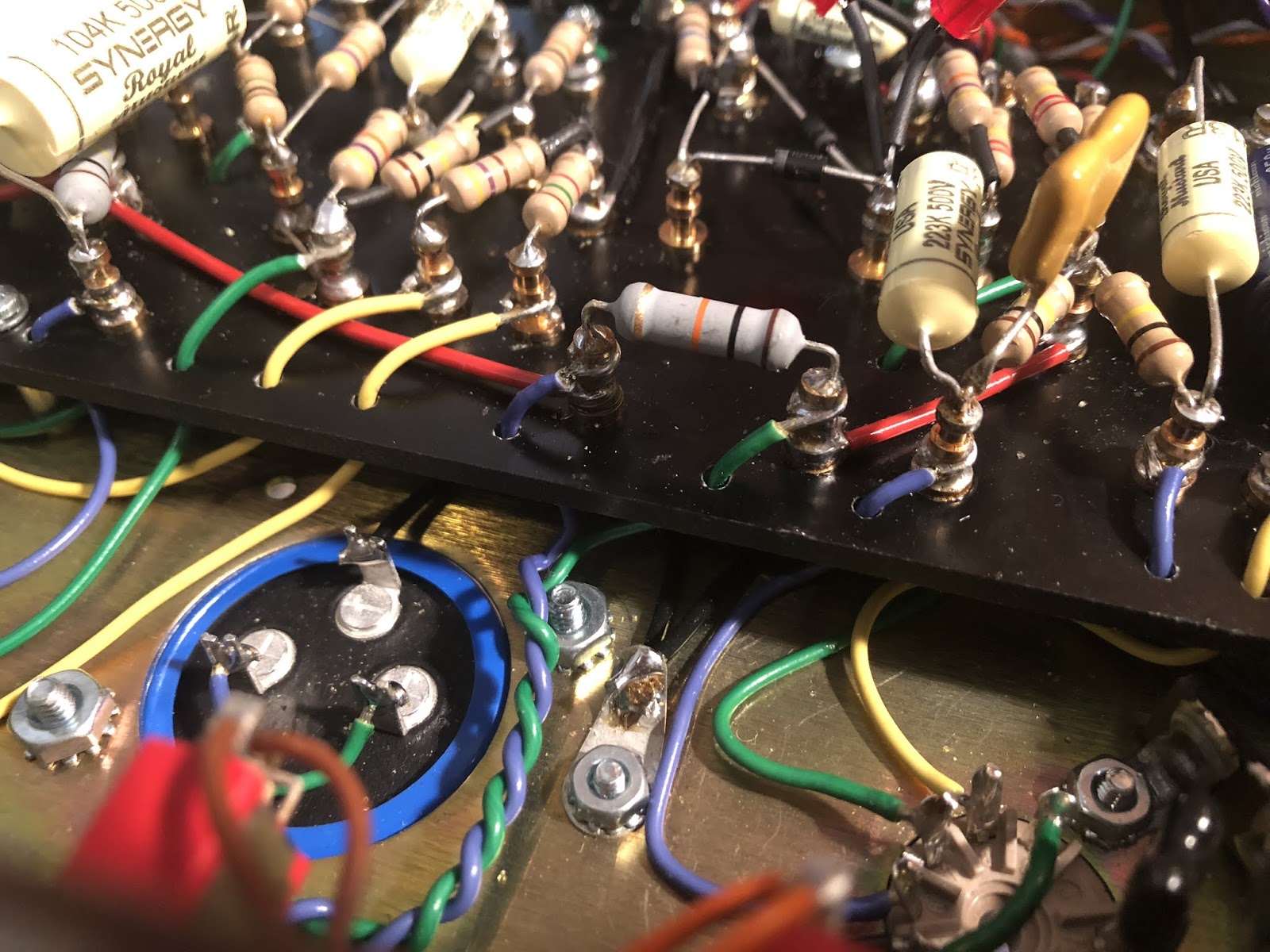
I've lost V2B. All my wiring connects as told by the DMM. I disconnected the 1M resistor to ground and it made no difference (in the air on the photo below). This is my OEM effects loop splice-out point. The SDM layout and SCH for the 2550X that I based my preamp off of are here:
TL 2550X layout R11.JPG
TL 2550X schemR11.JPG
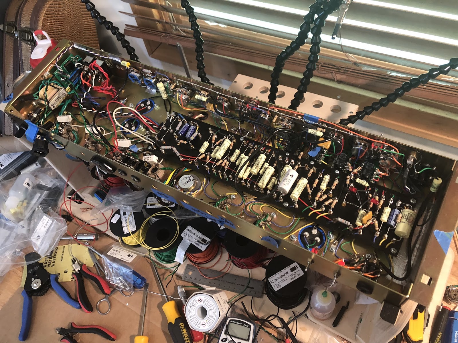
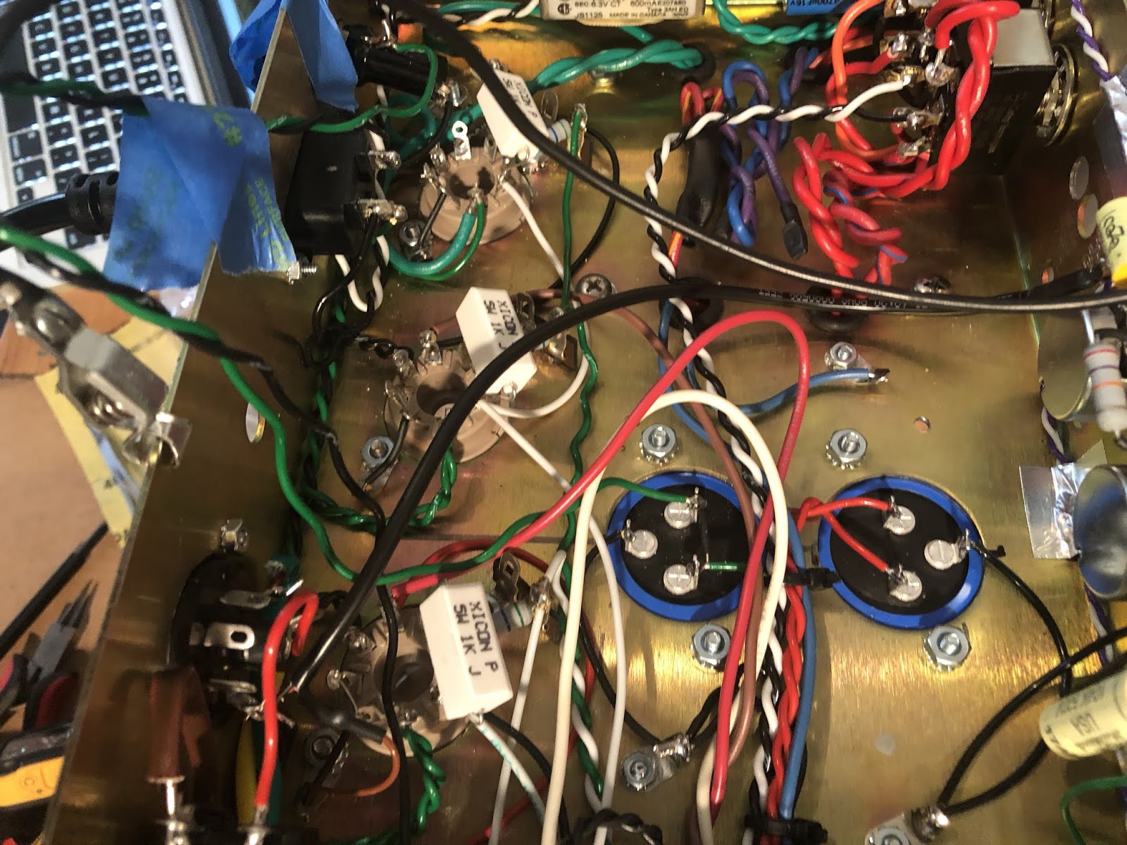
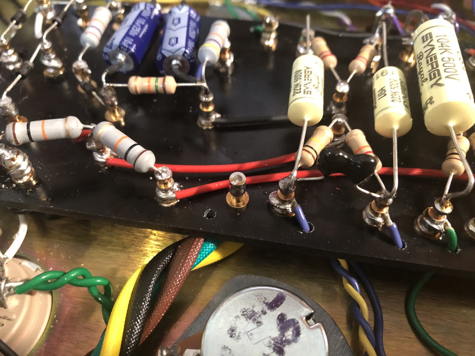
Here's a better shot of the board:

Image

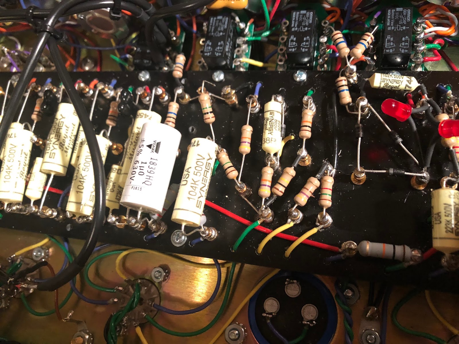
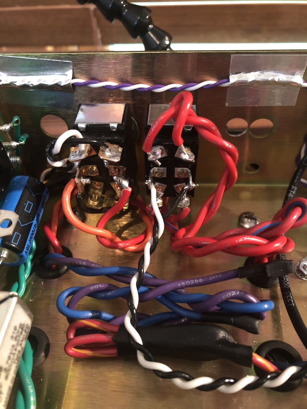
To help out, the relay on the right handles the channel-change, red/green LED voltage and the clean/lead volume pots; The next deals with the preamp circuitry; the third is the clipping circuit relay and the fourth handles the discreet tone stacks.

Also, the original layout has the Lead channel as the default channel (with no energy on the relays). I wanted the Clean as the default so I just swapped the appropriate connections on the relays.

The V2A pins all "talk to the speaker" when I measure them. V2B does not. In the original Jubilee, the V2A plate lead hits the .1 uF cap, then a 100K and then into the would-be effects loop with a 10K resistor to ground. I want this post 0.1 uF signal to go straight into the V2B grid, but there's no voltage after the V2A plate/power rail node.

Also, the LED section of the preamp remains unlit and the channel switch isn't working tone-wise. The relays switch to the individual channel controls, but the tone out of the speaker doesn't change hardly at all.

Any ideas? Bad 0.1 uF cap?

Note: I'm going to use a Metro ZL loop but it's not connected as of yet. The shielded cable is looped from the treble outputs back to the master volume.

What could be the problem/s here? Thanks. :mrgreen:
You do not have the required permissions to view the files attached to this post.
Just plug it in, man.
User avatar
ViperDoc
Posts: 1247
Joined: Tue Dec 24, 2019 2:21 am
Location: Idaho

Re: New amp power up concerns

Post by ViperDoc »

I discovered what I think is a bad relay board or board connection. The last relay that handles the tone stacks into the MV/Loop is stuck in the normal position. I changed it out for a new relay with the same results. The board has 5 VDC power and the ground connection switches in and out with my switches, so that's a bad relay board, yes? WHICH IS THE HARDEST ONE TO GET TO NOW THAT I HAVE ALL THAT OTHER [redacted] IN THERE. [redacted]!!!

ADD: I tested the diodes on the boards and they seem to give the same values and are confirmed to connect from each lead to their respective +/- connection on the board. Here's a SCH of my relay setup. Relays "1, 2 and 4" should be energized with the channel switch. #3 is for the clip. The only one that doesn't energize is #4, all the others work just fine. Why?
2555X RELAY POWER C.png
You do not have the required permissions to view the files attached to this post.
Last edited by ViperDoc on Sun May 31, 2020 7:34 pm, edited 3 times in total.
Just plug it in, man.
Post Reply