I've been studying the Sunn Sorado schematic ahead of my bass amp build and I have a puzzle. I'm going to be modding the design a skosh since I'm using a Antek donut for power a marshall plexi choke and will liekly also add a cathode follower ala SVT. I think you've talked me out of a PPIMV.
The schematic is here
https://el34world.com/charts/Schematics ... sorado.pdf
Specifically the 390 uF cap between the screen tap of the lower KT88 tube and the one (but not both of the UL taps) This is looking like a NFB ac input to the screen of the input of one side. This seems... odd. The schematic is a bit blurry and it actually looks like 390 uF, which would be insane, But if you look closer it looks like 390 uuF, or .000390 uF or 390pF?
If you look at the other Sunn schematics from that era, the 390 pF values makes way more sense and is inline with the 100S and Spectre schematics. Also it's likely pretty damn hard to find a 390uF cap, nonpolar at 600Vdc that is small enough to fit in an amp without wiring two electrolytics back to back.
Questions on Sunn Sorado NFB cap to UL tap
Moderators: pompeiisneaks, Colossal
-
mirage_indigo
- Posts: 84
- Joined: Thu Oct 02, 2014 3:34 pm
- Location: Longmont, CO
Questions on Sunn Sorado NFB cap to UL tap
We build because we must.
Re: Questions on Sunn Sorado NFB cap to UL tap
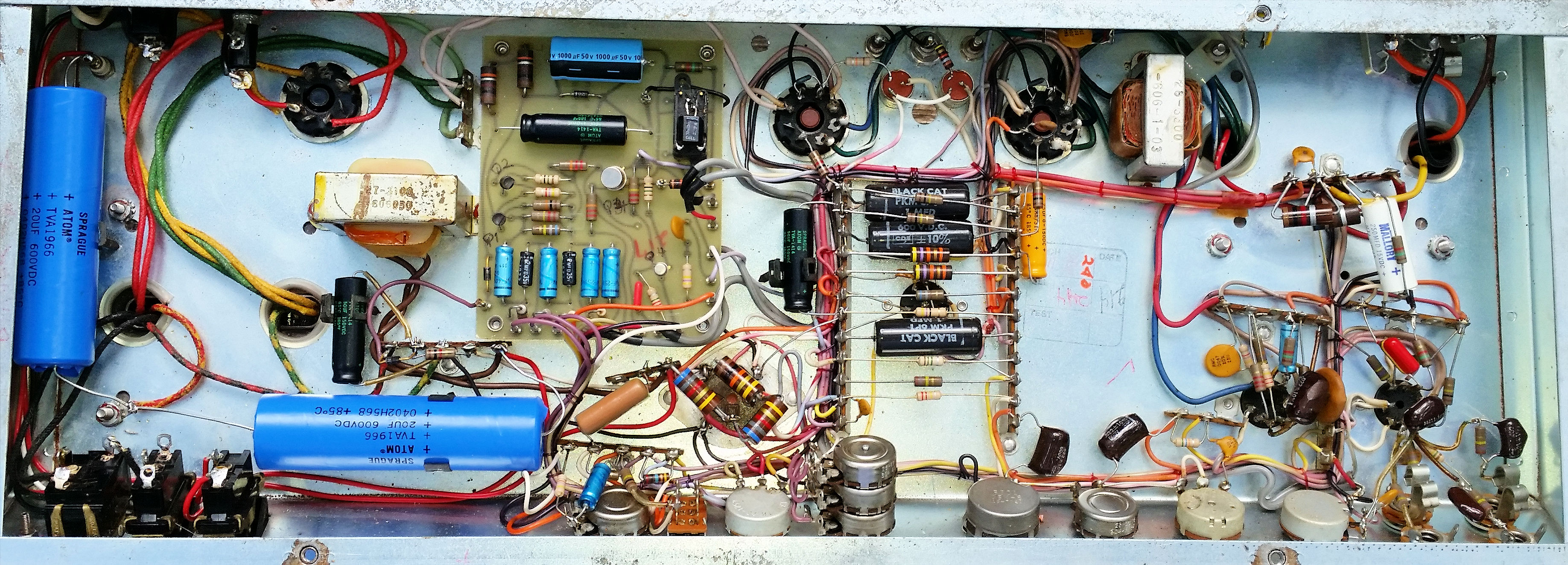
It is a 390pF cap. In the '60s "pF" "pico" was just beginning to become popular. "µµ"(micro micro or micky mic) was still being used. They both mean the same thing. That Sunn schematic you posted clearly shows 390µµ. And here's a pic that shows the 390pF mounted on the right power tube socket between pins 4 and 6. Pin 6 shows an orange wire.
http://sluckeyamps.com/sunn/sceptre1.jpg
http://sluckeyamps.com/sunn/sceptre1.jpg
-
mirage_indigo
- Posts: 84
- Joined: Thu Oct 02, 2014 3:34 pm
- Location: Longmont, CO
Re: Questions on Sunn Sorado NFB cap to UL tap
Thanks. What's odd is that schematic also uses pF other places (like the other feedback cap).
What V rating did you use on that cap? I was just going to use 630VDC since a) I already have a bunch and b) math is hard. The NFB point is at roughly DC ground, whereas the screens in UL are usually at somethign liek 66% VB+, which is going to be something slightly north of 500. So this seemed about right.
What V rating did you use on that cap? I was just going to use 630VDC since a) I already have a bunch and b) math is hard. The NFB point is at roughly DC ground, whereas the screens in UL are usually at somethign liek 66% VB+, which is going to be something slightly north of 500. So this seemed about right.
We build because we must.
Re: Questions on Sunn Sorado NFB cap to UL tap
That's the original cap and I have no idea about the voltage rating. 500V was popular back in the '60s for those ceramic picos. So was 1000V. If I had a bunch of 630V caps that's what I would use.
My Sceptre has 498V on the screens. I would NOT use a 500V cap to replace the original cap even if the original is 500V.
.
My Sceptre has 498V on the screens. I would NOT use a 500V cap to replace the original cap even if the original is 500V.
.
-
mirage_indigo
- Posts: 84
- Joined: Thu Oct 02, 2014 3:34 pm
- Location: Longmont, CO
Re: Questions on Sunn Sorado NFB cap to UL tap
I double checked on the rev two schematic and can confirm a 390 pF part. I think I bought a 1000VDC part. There aren't any rating values on the schematic except for the cathode bypass caps and one lone tone cap in the preamp and a couple odd resistors.
The Mouser order came in today, so I'm trying to finish up the schematic before I head on to the layout. I'm planning on using an Antek 100VA 200-0-200 donut in series, a 1650P hammond OT, 194G choke. The main filter caps are going to be 630v Solens as I've built almost everything with fast caps and really like em. Should have around 550 V+ at idle (I think)
Should be a beast with the only real change that additional cathode follower in there (and using different ps caps). Looking at the cathode follower now. Someone posted a good intermediate voltage rail at a lower 165VDC intermediate rail supply over in the dumbleland /SSS threads to power the top V+ of the cathode follower and I probably will do that here since I don't want 380v -> -55bias across a 12ax7. I'll likely use that.
We build because we must.
-
mirage_indigo
- Posts: 84
- Joined: Thu Oct 02, 2014 3:34 pm
- Location: Longmont, CO
Re: Questions on Sunn Sorado NFB cap to UL tap
I'm about to start the final mechanical planning for the build before drilling lots of holes, all the pieces parts are assembled.
The main changes from dead stock are:
- SS rectified using a bunch of hexfreds I had left over.
- Solen caps. YEs that's a 100uF solen can cap sitting on the chassis. I have 3 of em I bought like 15 years ago, may as well use em.
- I'm using a 100W Antek toroid 200-0-200 with the windings in series. According to Duncan's I should be getting about 510ish on the secondary after the choke. As such I'm going to drop the preamp voltage a tad using lightly larger 5W resistors after the main b+ feed. Probably ~40k instead of 33k. I'm using a hammond marshal choke whihc should be larger but otherwise about the same as the dynaco original.
- Since I have to use a bridge rectifier, I'll be going with a capacitively coupled bias supply, so I've been studying the old jmp800 schematic. Looks easy enough.
- I'll be using an input wiper style PPIMV with dual 250k pots in place of bias feed resistors.
Yes yes, I know, NFB + PPIMV = certain doom, except no one seems to be able to point out any actual problems with this arrangement other than it messes up a bias wiggle trem which I don't have. I talked myself out of cathode followers after the splitter since the concetina splitter essentially _is_ a pair of cathode followers.
The consensus on the internets about the Sunn Amps of this topology seems split between those who think they are ungodly hella loud and UNGODLY HELLA LOUD with more cuss words.
Should be fun. I'll post a layout and pdf schematic at some point as well as a .sch file once I figure out KiCad.
You do not have the required permissions to view the files attached to this post.
We build because we must.