I would like to know how to calculate the power requirements for a single ended amp. I know that you simply add up the individual current draw from each tube... but here is the twist: one channel - four stage pre (two 12AX7s, pretty close to a Trainwreck Express) and one power tube (optional swap out - 6K6, 6V6, 6L6, EL34, or KT88). I want to be able to run any one of the above mentioned power tubes. I'm just wondering if someone would be willing to break it down bit by bit, so that i can digest. I could post schematics if needed. Maybe some OT suggestions too?
As a second thought: Can anyone explain how to develop a PS for this amp with Duncan PS Design app. I'm pretty familiar with it but i would like to see an open discussion of it. Links to info would be helpful too.
Thanks in advance,
Tony
Power Transformer Help
Moderators: pompeiisneaks, Colossal
-
Super_Reverb

- Posts: 188
- Joined: Tue Dec 21, 2010 6:28 am
- Location: Indianapolis, USA
Re: Power Transformer Help
If I were building a SE amp with a KT88 option, I'd start with the power stage design as it draws the vast majority of current. You'll have to decide how much money you want to spend on OT and tubes and how much bias current you're going to run in your output tube.
A Hammond 125 GSE will let you run 100mA bias current max. with 25W power out.
http://www.drtube.com/datasheets/kt88-sed1999.pdf
Let's say you are using a Svetlana KT88 running 85mA plate bias current plus 5mA screen current with four preamp stages drawing another 3-4mA total.
Using Hammond 270BX-HX series (275-0-275) will give you 380-390VDC at the first filter cap stage.
I am running a 125ESE and a 270HX with a Tung Sol 6550 with three 12AX7 gain stages and a cathode follower driving the F/M/V tonestack. I have more than enough pre amp gain. 270EX would have been enough for this design, but I already had a 270HX.
Am running cathode bias with about 320 Ohms - it gives me 80mA bias current. This design is pushing the envelope, but Hammonds have some design margin.
One thing I have found with design is to get enough punch with this level of bias current, I had to run 100uF filter cap out of the silicon rectifiers to the OT B+ voltage lead.
Keep searching. There is a lot of good information out there.
rob
-
dorrisant

- Posts: 2790
- Joined: Tue Sep 21, 2010 1:27 pm
- Location: Somewhere between a river and a cornfield
- Contact:
Re: Power Transformer Help
Thanks for the response.
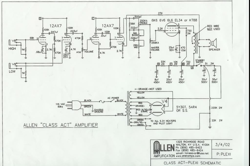
Ok... How about this schematic...
[IMG 680]http://i946.photobucket.com/albums/ad30 ... LmpwZw.jpg[/img]
Can anyone try the power supply with Duncan PSU II? When I try this one in particular, I end up with low HT for the preamp section. Too low I think. Maybe I'm missing something... I just want to verify that I'm on the right track with the design app (whether now or after corrected). You know... Teach me to fish... so to speak. This schematic is pretty close to what I want to do... At least the power amp section anyway.
Any takers?
Tony
Ok... How about this schematic...
[IMG
 680]http://i946.photobucket.com/albums/ad30 ... LmpwZw.jpg[/img]
Can anyone try the power supply with Duncan PSU II? When I try this one in particular, I end up with low HT for the preamp section. Too low I think. Maybe I'm missing something... I just want to verify that I'm on the right track with the design app (whether now or after corrected). You know... Teach me to fish... so to speak. This schematic is pretty close to what I want to do... At least the power amp section anyway.
Any takers?
Tony

Re: Power Transformer Help
Any transformer with 120mA-150mA HT current will be fine with any of those tubes. Personally, I would shoot for a PT with a 340+VAC secondary using a tube rectifier. The SE tube power transformers that I'm using are
360-0-360V@150mA, single all or parallel 6V6
5V @ 3.5A
6.3V @ 4.5A
Version #2, for parallel 6L6-KTxx
360V-0-360V@230mA
5V @ 3.5A
6.3V @ 4.5A
TM
360-0-360V@150mA, single all or parallel 6V6
5V @ 3.5A
6.3V @ 4.5A
Version #2, for parallel 6L6-KTxx
360V-0-360V@230mA
5V @ 3.5A
6.3V @ 4.5A
TM
-
Super_Reverb
- Posts: 188
- Joined: Tue Dec 21, 2010 6:28 am
- Location: Indianapolis, USA
Re: Power Transformer Help
This is another issue, but the 470K Ohm resistor connected to grid of third gain stage in preamp appears to be connected incorrectly.
Shouldn't the resistor be connected between pin 7 and gnd, rather than to cathode of second pre stage?
rob
Shouldn't the resistor be connected between pin 7 and gnd, rather than to cathode of second pre stage?
rob
-
dorrisant
- Posts: 2790
- Joined: Tue Sep 21, 2010 1:27 pm
- Location: Somewhere between a river and a cornfield
- Contact:
Re: Power Transformer Help
Rob - That is odd... wouldn't the 470k resistor and the 4.7k cathode resister combine for a series resistance as a grid stopper for stage 3 input... Maybe there is some sort of feedback being used here. I was more concerned with the power amp and supply sections. It is a great question though...
Has anyone put the power supply values in the Duncan PSU to see what voltages you get at stage 1,2,3,etc.? Maybe they are not too low, but I would like to see if I'm doing it right or not.
Tony
Has anyone put the power supply values in the Duncan PSU to see what voltages you get at stage 1,2,3,etc.? Maybe they are not too low, but I would like to see if I'm doing it right or not.
Tony

Re: Power Transformer Help
Yes, "local" NFB......using the bottom of the voltage divider to feed a bit of signal back into the cathode of the previous stage.Maybe there is some sort of feedback being used here
G
-
dorrisant
- Posts: 2790
- Joined: Tue Sep 21, 2010 1:27 pm
- Location: Somewhere between a river and a cornfield
- Contact:
Re: Power Transformer Help
Thanks G...
I don't mind getting off topic a little, if you want to drop some knowledge on us... Even though the pre is not like the one I want to use, I am still interested in the why and how of the NFB... Btw... Is it also being used as a grid stopper? I think it could be for both.
The circuit works well from what I understand... Not in production anymore, but the reviews were glowing... I don't think anyone would expect less from Allen amps.
Anyway... PSU app - I don't know what I need to insert for the individual loads for each power supply tap or even what the load at the end needs to be changed to. Or how to insert all the values of a transformer. Can we pick out a Hammond so we would have some absolute values to enter and start with. I hate to be so insistent on PSU II, but I am having trouble finding any good help on it in particular. Maybe someone has a link to a tutorial or something like that... Or just tell me... "no you big dummy... Not like that... Like this..." Don't worry, I doubt you could hurt my feelings. I just want to be able to rely on the results I get from this app. If it would work out better to use a different transformer, go right ahead. I'll just follow whatever example you want to work with.
Tony

Re: Power Transformer Help
The local NFB is is going to cancel a certain amount of freq's and lower some gain from that third (or second from the low input) cascaded stage and also act a little bit like a snubber which should help also minimize parsitic oscillation after 3 gain stages. The 100k resistor before the 4th stage will act as a grid stopper and the voltage divider of it and the 470k + 4.7k will lower signal gain going into 4th stage. The rather cool bias of the third stage will also help give a smoother overdrive w/ the tube being closer to cut-off and help keep all of the hotter biased stages from becoming too brittle sounding and lending better sustain & tone.
There's calculations for much of this if you check Merlin or Keuhnel's books.
There's calculations for much of this if you check Merlin or Keuhnel's books.