Thx for your help Mark. Big, clear pictures alway help.M Fowler wrote:See the twisted green filament wires on my K60 going to the pilot light and then on to the power tubes.
Mark
My Very First Ever Build AA764 Vibro Champ. (Cab is here)
Moderators: pompeiisneaks, Colossal
Re: My Very First Ever Build AA764 Vibro Champ. (Cab is here)
Re: My Very First Ever Build AA764 Vibro Champ. (Cab is here)
And that's what I needed to know.M Fowler wrote:Take a twisted pair of wire and go from the green filament wires on your 6.3v pilot light socket to the first power tube socket. Hook the wires to pin 2 and pin 7. Does not matter which wires goes to these two first pins. Do not solder them yet as you need to make another twisted pair of wires to go between your power tube sockets. Same thing but this time wire from pin 2 to pin 2. The other wire goes from pin 7 to pin 7.
It does not matter when going from your power tube to the preamp tube sockets which wire you use. But when you start on the preamp tube sockets you keep those preamp sockets in polarity going from pin 9 to pin 9 and pins 4/5 are together to pin 4/5 next preamp socket. Just trim off more wire from your twisted pair to go through both pins. Some people bend them together your choice.
Mark
Does pin 7 of the power tubes amp get hooked up to pin 9 on the pre-amp tubes?
Re: My Very First Ever Build AA764 Vibro Champ. (Cab is here)
You can run the two 100 Ohm resistors from the pilot light to a ground lug, or put them on pins 2 and 7 on the octal and then to a ground lug. If your transformer has a center tap for the heater wires, you don't need the resistors.
briane wrote:... it really is a journey, and you just can't farm out the battle wounds.
Re: My Very First Ever Build AA764 Vibro Champ. (Cab is here)
Normster wrote:You can run the two 100 Ohm resistors from the pilot light to a ground lug, or put them on pins 2 and 7 on the octal and then to a ground lug. If your transformer has a center tap for the heater wires, you don't need the resistors.
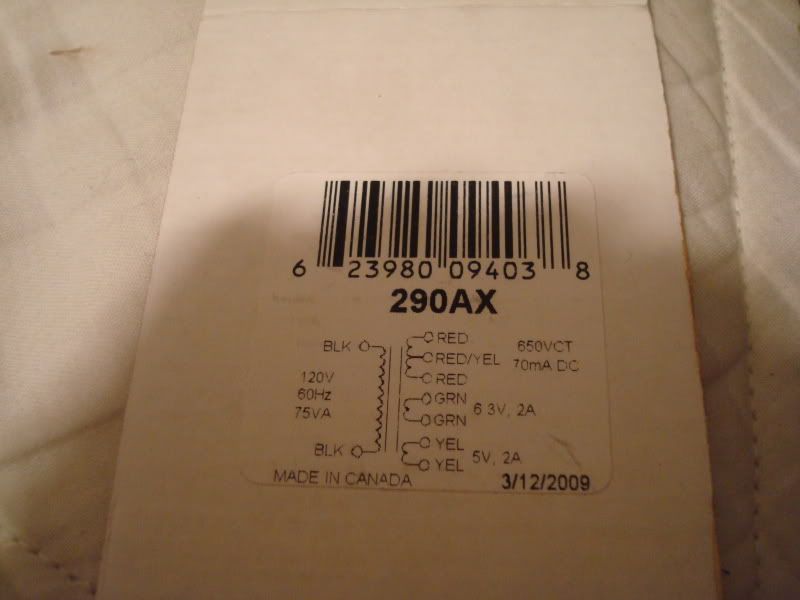
This is the diagram from the box from my transformer. The red yellow wire I hooked up to a ground lug. I'm assuming that is the center tap? Am I wrong?
[IMG:800:600]http://i114.photobucket.com/albums/n271 ... C01974.jpg[/img]
Re: My Very First Ever Build AA764 Vibro Champ. (Cab is here)
On the Champ and Vibrochamp, yes. This is the stock switch.M Fowler wrote:Did Fender use that type of on/off switch?
Mark
Re: My Very First Ever Build AA764 Vibro Champ. (Cab is here)
The red/yellow is the center tap for HT. Your transformer does not have a center tap for the heaters so you'll need to use the 100 ohm resistors if you wire your heaters as Mark suggested. This creates an "artificial" center tap.
briane wrote:... it really is a journey, and you just can't farm out the battle wounds.
Re: My Very First Ever Build AA764 Vibro Champ. (Cab is here)
oh ok, so If wire one of the green 6.3 wires to the light and ground the second one then I don't need the resistors, right? But if both wires add up to 6.3 then how can just one wire provide the 6.3 v the wires need?
Re: My Very First Ever Build AA764 Vibro Champ. (Cab is here)
No, you run one 100R resistor from each green wire to ground.
Run the green wires to the first power tube.
From the pins that the green wires attach to, solder one 100R 2w resistor
to each of those same two pins, connect the other end of the resistors to a ground lug on the socket mounting bolt under the nut.
Look at this diagram
Run the green wires to the first power tube.
From the pins that the green wires attach to, solder one 100R 2w resistor
to each of those same two pins, connect the other end of the resistors to a ground lug on the socket mounting bolt under the nut.
Look at this diagram
You do not have the required permissions to view the files attached to this post.
Tom
Don't let that smoke out!
Don't let that smoke out!
Re: My Very First Ever Build AA764 Vibro Champ. (Cab is here)
Will do! Thx yet again,Structo wrote:No, you run one 100R resistor from each green wire to ground.
Run the green wires to the first power tube.
From the pins that the green wires attach to, solder one 100R 2w resistor
to each of those same two pins, connect the other end of the resistors to a ground lug on the socket mounting bolt under the nut.
Look at this diagram
Re: My Very First Ever Build AA764 Vibro Champ. (Cab is here)
Another update and yet another rookie question.
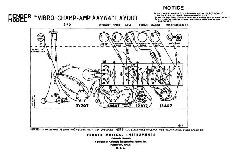
So I wired most of it but I need to wire the input jacks. In the diagram here...
Are those shorting jacks? What is tip and sleve in the pic? (It shows three dots per input that's why I'm a bit confused)
[IMG:800:536]http://i114.photobucket.com/albums/n271 ... champ1.jpg[/img]
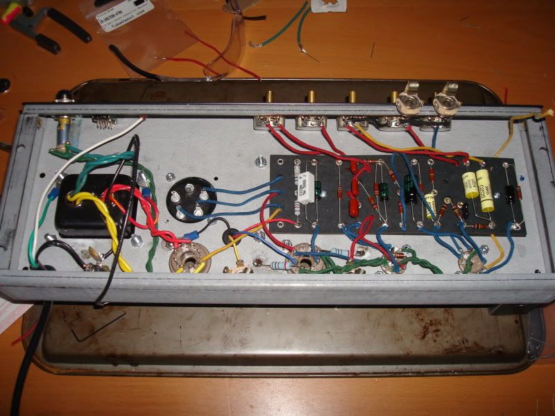
And a picture of where Im at now. I need to wire and ground 2 resistors on the pots and to wire the ac cord to the switch. If you guys spot anything out of place feel free to correct me.
Many thanks.
[IMG:800:600]http://i114.photobucket.com/albums/n271 ... C01976.jpg[/img]
So I wired most of it but I need to wire the input jacks. In the diagram here...
Are those shorting jacks? What is tip and sleve in the pic? (It shows three dots per input that's why I'm a bit confused)
[IMG:800:536]http://i114.photobucket.com/albums/n271 ... champ1.jpg[/img]
And a picture of where Im at now. I need to wire and ground 2 resistors on the pots and to wire the ac cord to the switch. If you guys spot anything out of place feel free to correct me.
Many thanks.
[IMG:800:600]http://i114.photobucket.com/albums/n271 ... C01976.jpg[/img]
Re: My Very First Ever Build AA764 Vibro Champ. (Cab is here)
Yes it does show switching or shorting jacks.
That way when there is not a cord plugged in it shorts out the grids of the tube, silencing the input.
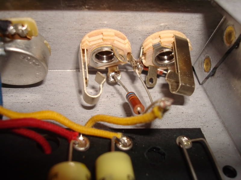
Also there is a 1M resistor that is hard to make out there on the right hand jack (looking at the layout).
It goes from the right lug to the lug that is connected to the other jacks middle lug.
Additionally it might be a good idea to use shielded cable from the 68K resistors to pin 2 on the tube.
Also it wouldn't hurt to shield the wire from the volume pot to pin 7.
That way when there is not a cord plugged in it shorts out the grids of the tube, silencing the input.
Also there is a 1M resistor that is hard to make out there on the right hand jack (looking at the layout).
It goes from the right lug to the lug that is connected to the other jacks middle lug.
Additionally it might be a good idea to use shielded cable from the 68K resistors to pin 2 on the tube.
Also it wouldn't hurt to shield the wire from the volume pot to pin 7.
Tom
Don't let that smoke out!
Don't let that smoke out!
Re: My Very First Ever Build AA764 Vibro Champ. (Cab is here)
Something that is easy to miss is the points [A] and points [X]
So you connect [A] to [A] and [X] to [X].
So pin 5 on the 6V6 goes to point [X] on the circuit board where the 220K resistor and .02uf cap is. See the hole by the cap and resistor junction on the board? The wire feeds from underneath to that point to pin 5.
There is also a 330pf cap (ceramic disc ) from pin 5 to pin 8 on the 6V6.
And [A] is the junction of the two 100K plate resistors of V1 to point [A] which is the 10K resistor on the upper left of the circuit board.
That connection would probably be best to do under board.
Hope this helps
Tom
Don't let that smoke out!
Don't let that smoke out!
Re: My Very First Ever Build AA764 Vibro Champ. (Cab is here)
Thank you Structo. That was ALL very helpful.

Re: My Very First Ever Build AA764 Vibro Champ. (Cab is here)
Jack wiring can be hard to wrap your mind around.
You do not have the required permissions to view the files attached to this post.
Re: My Very First Ever Build AA764 Vibro Champ. (Cab is here)
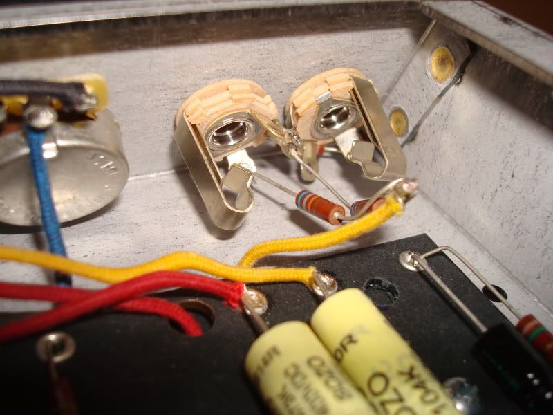
I'm all done wiring this thing up however I hooked it up to a 4 ohm cab and I'm getting no sound.
It didn't blow up when I started it up and there was no hum or anything crazy but there was no sound either.... :'(
Checked voltage on a couple of spots and they were in the 365-370 range. (I checked the cap can, screen grid)
I'm thinking I might have not wired the inputs properly. Would you guys mind taking a peek?
Edit: Also I just noticed the volume pot needs to be grounded and it's not. Everything else I think should be wired good.
[IMG:800:600]http://i114.photobucket.com/albums/n271 ... C01979.jpg[/img]
[IMG:800:600]http://i114.photobucket.com/albums/n271 ... C01981.jpg[/img]
PS Almost done guys!