It's not clear to me what you have there. You say the OT secondary is 8 ohms only, but there are three leads. I would put some AC (filament voltage say) on the primary, measure the primary voltage and the voltages on the secondary to determine the impedances.
You will want to keep the negative feedback loop, but you may have to adjust the 100k resistor value down to 72k if indeed you only have an 8 ohm output.
Ampeg SB12 Bass Amp Build
Moderators: pompeiisneaks, Colossal
-
martin manning

- Posts: 14308
- Joined: Sun Jul 06, 2008 12:43 am
- Location: 39°06' N 84°30' W
-
dawsonaudio
- Posts: 110
- Joined: Mon Jun 30, 2014 6:43 pm
Re: Ampeg SB12 Bass Amp Build
Here's a link to another discussion in regards to the same OT that I'm using.
http://www.audiokarma.org/forums/archiv ... 59947.html
It is the same transformer I used in my Surpo Amp build and is hooked up the same way as in the Hammond M3 Organ. Both the green and yellow wires are connected to the speaker voice coil terminals and the black wire is tied to ground. Not sure if that gives a quick explanation.
OK guys, here's your answers:
The full secondary winding of the output transformer is 8 ohms. The black center tap lead is in fact a center tap of the secondary winding. In the Hammond organ setting, it needs to be grounded. In a more modern setting like a guitar amp, it can likely be disregarded. More on why that is in a moment.
In electromagnet speakers, it is very common to not only wind the "field" coil on the magnetic structure (which forms the basis of the electromagnet), but also a separate little "hum-buck" winding with it as well. This hum-buck winding is wired in series with the voice coil winding buck style, and is designed to help cancel the 120 hum that would otherwise be reproduced in the speaker cone if relatively unfiltered DC is used to power the electromagnet. Were it powered with well filtered DC, the hum buck coil would not be needed, or could be disconnected if originally wired in place. In the Hammond spinet models, the field coil appears right at the output of the rectified DC, so 120 Hz ripple is significant, requiring the hum buck coil to help silence the hum in the speaker.
As for the grounded center tap of the output transformer, that serves the larger purpose of driving external tone cabinets. These are connected to a Hammond organ with a very heavy gauge six conductor cable. Each tone cabinet has a 5 and 6 connector plug on its amplifier chassis (one male, one female), that allows a cable supplying power and signal to be connected to it, and also an additional cable to send the power and signal on to additional tone cabinets. In this way, numerous tone cabinets could be connected to one organ, and all controlled by it.
Now these cables have no shielding to them, or internal shielded cable to carry the signal. They just send the power AND the signal through the internal conductors of this six lead cable that connects between the organ and first tone cabinet, and then on to other possible cabinets. Normally, this would cause tremendous hum with the signal and power wires all contained within one long cable. But what Hammond did to address this, was to:
1. Drive the tone cabinet power amplifiers directly from the speaker of a spinet model organ. This means the drive signal represents a very low impedance (8 ohms), and therefore will not be very sensitive to picking up induced hum in the cable.
2. By using speaker level signal voltage to drive the tone cabinet amplifiers, their gain could be made very low to further minimize the pick up of hum in the connecting cable.
3. Drive the tone cabinet with a balanced drive signal relative to ground. By using a balanced signal connection (just like low impedance mic connections use), any hum induced into the balanced signal leads within the cable would cancel out at the balanced input of the tone cabinet amplifier.
But to have a balanced signal to supply the tone cabinet, a balanced signal first has to be created. Enter the center tap of the ouput transformer. With the center tap of the secondary grounded, the actual speaker leads now represent a balanced signal with respect to ground, that can be used to drive the balanced input of the tone cabinet amplifiers, through the big connecting cable, without introducing any significant hum. But Hammond capitalized on this connection even further.
If you examine the schematic of a true Hammond tone cabinet amplifier, you see that they are push-pull, but don't contain a phase inverter circuit. That's because they don't need one. They can simply take the balanced signal applied to the tone cabinet from the organ, amplify it with a push-pull driver stage, and then drive the output stage in normal fashion.
The whole affair was pretty ingenious for its day, and worked very well. They only used 5 of the 6 conductors in the cable -- two to power the tone cabinet amplifier, a ground connection, and the two balanced signal drive leads.
In more modern times, Leslie amplifiers contain a phase inverter stage, and are driven with a standard unbalanced drive signal -- still from the speaker as before. But they found that the low gain of the tone cabinet amplifier, and the low impedance drive was enough to minimize the hum in spite of the unbalanced drive connection, which then freed up an additional lead to use with the unused sixth lead to control the motor spin speed in Leslie type cabinets from the organ console.
So, the center tap was very much required in the organ setting -- but only for the external purpose of driving a tone cabinet. Used in other settings, the center tap lead (which is really a 2 ohm tap relative to either of the other two leads) could simply be disregarded -- unless you're going for one of the old Super Reverb style Fender amps that had four 8 ohm speakers all connected in parallel for a 2 ohm load!!
I hope this helps.
Dave
-
martin manning
- Posts: 14308
- Joined: Sun Jul 06, 2008 12:43 am
- Location: 39°06' N 84°30' W
Re: Ampeg SB12 Bass Amp Build
Ok, so the black lead is a center tap on the OT secondary. You should ignore that and use the other two for an 8-ohm speaker. Which one of those should be treated as ground I don't know without some measurements. You can guess, and be ready to swap them if you end up with positive feedback and squealing.
-
dawsonaudio
- Posts: 110
- Joined: Mon Jun 30, 2014 6:43 pm
Re: Ampeg SB12 Bass Amp Build
Just found this project that uses the same OT. Looks like the green wire is grounded. Would I wire in the negative feedback loop section off the yellow wire with the 72k resistor?
[img 748]http://www.solorb.com/elect/musiccirc/h ... tor1r3.jpg[/img]
[img
 748]http://www.solorb.com/elect/musiccirc/h ... tor1r3.jpg[/img]
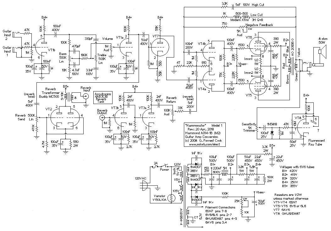
Re: Ampeg SB12 Bass Amp Build
I have an AO-63 amp with an OT that has a grounded ct on the 8Ω secondary also. OT number is AO-30072-1. It's driven by a pair of 7591s and sounds very nice with an Ampeg B15 preamp. I have to use an isolated speaker jack.
You do not have the required permissions to view the files attached to this post.
-
martin manning
- Posts: 14308
- Joined: Sun Jul 06, 2008 12:43 am
- Location: 39°06' N 84°30' W
Re: Ampeg SB12 Bass Amp Build
If the colors are labeled accurately in that schematic I think ground the green, and take the FB from the yellow with a 72k resistor.dawsonaudio wrote:Just found this project that uses the same OT. Looks like the green wire is grounded. Would I wire in the negative feedback loop section off the yellow wire with the 72k resistor?
Last edited by martin manning on Fri Jul 03, 2015 5:46 pm, edited 3 times in total.
-
dawsonaudio
- Posts: 110
- Joined: Mon Jun 30, 2014 6:43 pm
Re: Ampeg SB12 Bass Amp Build
It looks like, to me anyway, that the green is grounded to the sleeve.
-
martin manning
- Posts: 14308
- Joined: Sun Jul 06, 2008 12:43 am
- Location: 39°06' N 84°30' W
Re: Ampeg SB12 Bass Amp Build
Ok, I'm reversing myself. The green is grounded, but you have a different inverter and feedback arrangement. After more consideration, I now think the net result of the phase reversals is the same. Keep the primary colors as labeled in the Ampeg schematic.
-
dawsonaudio
- Posts: 110
- Joined: Mon Jun 30, 2014 6:43 pm
Re: Ampeg SB12 Bass Amp Build
...and still keep the negative feedback loop as you suggested with the changed 72k resistor?
-
martin manning
- Posts: 14308
- Joined: Sun Jul 06, 2008 12:43 am
- Location: 39°06' N 84°30' W
Re: Ampeg SB12 Bass Amp Build
Yes. The 72k is something that you may want to adjust to taste, given you are working with a different transformer. BTW, without the NFB the phasing of the OT windings wouldn't matter.
-
dawsonaudio
- Posts: 110
- Joined: Mon Jun 30, 2014 6:43 pm
Re: Ampeg SB12 Bass Amp Build
Sorry to revisit this again.
On the output transformer that I'm using, I am reading continuity from the black wire (c/t) to the the yellow and green output wires. This is with nothing connected. When the black wire is grounded to the chassis, both the yellow and green, as expected, are showing continuity to ground.
Will the negative feedback loop be affected by having the yellow also carrying ground? And since the black wire (c/t) seems to be internally connected to the yellow and green wires, could I utilize it as the connection to ground? This is how it is connected in my Supro 1624t as I compared it's connection points and got the same readings.
-
martin manning
- Posts: 14308
- Joined: Sun Jul 06, 2008 12:43 am
- Location: 39°06' N 84°30' W
Re: Ampeg SB12 Bass Amp Build
The black wire is a center tap, connected to the secondary winding at the mid point between the yellow and green. You do not want to ground black and yellow, as that would short half of the secondary.
The simplest thing to do is leave the black wire unconnected, and treat the yellow and green leads as a single 8-ohm secondary. You could ground the black lead, connect the other two to the speaker, and reduce the feedback resistor to 50k, but then you would have to isolate the speaker jack's sleeve terminal from ground.
The simplest thing to do is leave the black wire unconnected, and treat the yellow and green leads as a single 8-ohm secondary. You could ground the black lead, connect the other two to the speaker, and reduce the feedback resistor to 50k, but then you would have to isolate the speaker jack's sleeve terminal from ground.
-
dawsonaudio
- Posts: 110
- Joined: Mon Jun 30, 2014 6:43 pm
Re: Ampeg SB12 Bass Amp Build
Ok...I'll keep the black (c/t) wire unconnected from ground and treat the yellow and green wires as you suggested with the yellow lead connected to the negative feedback loop 72k resistor.
I am getting ready to turn things on, but before I do, I have never biased an amplifier before. I've adjusted the cathode resistor in my other amp to taste but that is a little different I assume. What would be a good starting point to set the adjustable resistor so I don't cook my output tubes at first start up? I've got a mains secondary voltage of 380v at each side of the rectifier socket without any tubes plugged in if that helps any.
I'm going to triple check all my connections first and do some reading on biasing tube amps. Any other suggestions would be appreciated.
Thanks again for all the help here.
Nate
-
martin manning
- Posts: 14308
- Joined: Sun Jul 06, 2008 12:43 am
- Location: 39°06' N 84°30' W
Re: Ampeg SB12 Bass Amp Build
The first thing to do is put the rectifier tube in, power up, and measure the plate and bias voltages. If you have a light bulb current limiter, it would be a good idea to use it the first time you power up with the rectifier in, then take it out when you want to measure voltages.
Check the bias voltage at the extremes of the bias pot adjustment. You'll need something around -20V to bias the 7591's per the data sheet, so look for a range of +/- 5 to +/- 10V around that. Leave the pot set for the most negative voltage.
You will need some way to measure idle current. The easiest way is by grounding the 7591 cathodes through 1 ohm, 1% resistors so the voltage you measure on the cathodes will be numerically equal to current in amps. Another way is to measure the DC resistance of each half of the OT primary, and use that resistance and the measured voltage drop at idle conditions to calculate anode current. This requires the extra step of converting the desired idle current to a target voltage drop across each side of the primary.
A good place to start for the idle current is 70% of maximum plate dissipation, which for 7591's is 19W. The idle current would then be 0.7*19W/Va, where Va is plate voltage. For example, if you have 400V for Va, then the desired idle current would be 0.7*19W/400V = 0.033A.
To set the bias, put the power tubes in, clip your meter to the terminals where you are going to measure voltage. Turn power on and let the filaments warm up. Finally, dial up the bias pot until the target voltage is reached.
-
dawsonaudio
- Posts: 110
- Joined: Mon Jun 30, 2014 6:43 pm
Re: Ampeg SB12 Bass Amp Build
So I turned on the amp with the 5ar4 in and no other tubes and got a pretty high plate reading of 515 vdc. I turned off the amp and discharged the caps which are rated at 450 vdc. The field coil speaker was also hooked up. I didn't have a chance to measure the bias voltage as I was concerned about the plate voltage.
So before I proceed, is this plate voltage too high? I assume that once the tubes are installed the voltage will drop. Just want to be safe here and not damage anything before I proceed further.
So before I proceed, is this plate voltage too high? I assume that once the tubes are installed the voltage will drop. Just want to be safe here and not damage anything before I proceed further.