The schematic doesn’t match the layout in terms of the preamp tube labels. Am I correct in assuming you hear pops at V2, pins 1, 2 and 3; and you do not hear pops at V2, pins 7, 8 and 9?
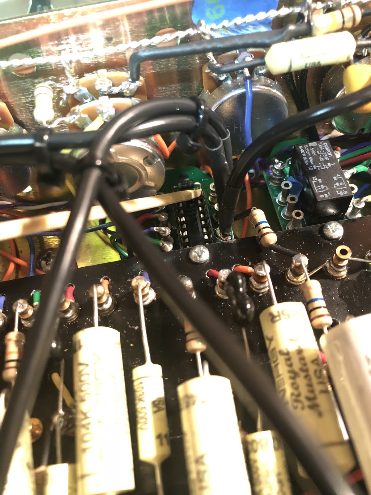
I think maybe I’ve spotted the issue. You said there is no efx loop in the build at the moment, is that right? If so, did you add a connection to bridge the gap where the loop jacks should be? I see the junction of the 100k and 10k resistors in your build (where the efx send jack would connect), and it doesn’t look like anything else is connected there. Shouldn’t there be a connection from there to the 0.1uF cap going into the grid of the next stage (IOW, where the efx return jack connects)?
New amp power up concerns
Moderators: pompeiisneaks, Colossal
-
JazzGuitarGimp

- Posts: 2357
- Joined: Mon Jul 23, 2012 4:54 pm
- Location: Northern CA
Re: New amp power up concerns
Lou Rossi Designs
Printed Circuit Design & Layout,
and Schematic Capture
Printed Circuit Design & Layout,
and Schematic Capture

Re: New amp power up concerns
Thanks. Youre right, I deleted the pre- and post-loop resistors except for the 1M to ground. See the KiCAD schematic I posted earlier in this thread. The V2A plate now hits the first 0.1uF cap. On the other end of that cap, there's a green wire that comes off that turret, goes under the board and then directly into the V2B grid. The wiring tests continuous there with my DMM.JazzGuitarGimp wrote: ↑Sun May 31, 2020 6:27 pm The schematic doesn’t match the layout in terms of the preamp tube labels. Am I correct in assuming you hear pops at V2, pins 1, 2 and 3; and you do not hear pops at V2, pins 7, 8 and 9?
I think maybe I’ve spotted the issue. You said there is no efx loop in the build at the moment, is that right? If so, did you add a connection to bridge the gap where the loop jacks should be? I see the junction of the 100k and 10k resistors in your build (where the efx send jack would connect), and it doesn’t look like anything else is connected there. Shouldn’t there be a connection from there to the 0.1uF cap going into the grid of the next stage (IOW, where the efx return jack connects)?
Last edited by ViperDoc on Sun May 31, 2020 9:30 pm, edited 1 time in total.
Just plug it in, man.
Re: New amp power up concerns
I found that the "fourth" relay socket pin is disconnected from the ground supply. Either I forgot to solder it or it is internally broken. Either way, I either cut a hole in the chassis to add solder from underneath or I disconnect everything and try to pull it out. If the socket itself is bad, how do you pull one of those off with 8 connections on the board?
ADD: I pulled this relay board and I'd overlooked soldering THAT ONE PIN. Operator error. Likely got distracted in Dad-mode and forgot to check it. Lesson learned.
ADD: I pulled this relay board and I'd overlooked soldering THAT ONE PIN. Operator error. Likely got distracted in Dad-mode and forgot to check it. Lesson learned.
Just plug it in, man.
Re: New amp power up concerns
OK, I pulled out that relay board and put in a new one. In testing, everything is well connected and put it back together with the same tonal results. Still no V2. There is very likely a problem with my circuit, but I noticed something that surprised me: the possibility of flux insulation on some of the contacts. I tested my tube heaters to assess that my tubes were actually getting charges on both sides. When I tested for heater AC voltage, the DMM would read in and out depending on where I put the probe. In my first builds, I used a flux wax from the hardware store. It works decently well, but accumulated a burnt carbon crud over time on the iron. For this build I switched to a rosin flux liquid I bought from Tube Depot and have dispensed it with a fine needle tip. Once I started using that, the carbon crud on my iron has all but disappeared. I do notice that it's quite thick, though. Might need some thinning with EtOH. Do any of you use this? I never noticed flux-blocking with the wax.
https://tubedepot.com/products/liquid-rosin-flux
I'm going to reheat every pin on the board and see what happens...
https://tubedepot.com/products/liquid-rosin-flux
I'm going to reheat every pin on the board and see what happens...
Last edited by ViperDoc on Mon Jun 01, 2020 5:01 pm, edited 1 time in total.
Just plug it in, man.
-
dorrisant

- Posts: 2790
- Joined: Tue Sep 21, 2010 1:27 pm
- Location: Somewhere between a river and a cornfield
- Contact:
Re: New amp power up concerns
Don't know if someone covered this... Those LEDs will not light up until there is signal passing by them. They are clippers tied to ground.
"Education is what you're left with after you have forgotten what you have learned" - Enzo
Re: New amp power up concerns
True that, thank you. I don't notice any activity on them when I test the amp on either channel. If I test them with my DMM on diode mode, they light up like a Christmas tree.
Just plug it in, man.
Re: New amp power up concerns
Well, I may have to call this thing a total loss. I've been reheating my turrets one by one to try and ensure I have good contacts and now the amp has no sound whatsoever. The lights are all on but no one is home. I was really hoping this would have turned out better! I noticed the flux I used blocked out some of the turret bases so I couldn't make contact through them. I've tinned *every wire tip* using it and my solder. How to find where it might be blocking the chain now is a journey for another time, I think. Too bad. This project was quite audacious, I'll own that, but after all my work--despite having several wins on this project--it's a dud. Thanks for all your interest and help anyway, guys. It is much appreciated.
Just plug it in, man.
-
pompeiisneaks

- Site Admin
- Posts: 4244
- Joined: Sat Jan 14, 2017 4:36 pm
- Location: Washington State, USA
- Contact:
1 others liked this
Re: New amp power up concerns
Even if you don't have an oscilloscope, you can still see where the signal drops using a DMM. Put it on ac volts, put in some kind of signal, and see exactly where you lose amplification. At the input grid of a stage you should see some known voltage, and then at the other side of the coupling cap of the output after the anode, you should see a significantly higher output (or at least the same as went in in some setups, as they're just designed to perform a different task like a cathode follower where the output should be very slightly less than input but to recover for losses of a tone stack etc. )
You should be able to see exactly where the loss happens and see what in that specific gain stage is then the fault. I did a video showing the basics of this idea so you can see how it works. The values differ from DMM to scope because scopes show raw output but DMM's do RMS output.
~Phil
You should be able to see exactly where the loss happens and see what in that specific gain stage is then the fault. I did a video showing the basics of this idea so you can see how it works. The values differ from DMM to scope because scopes show raw output but DMM's do RMS output.
~Phil
tUber Nerd!
-
Mac Dillard
- Posts: 28
- Joined: Sun Jun 23, 2019 9:51 pm
Re: New amp power up concerns
build yourself this simple audio probe:https://www.diystompboxes.com/pedals/debug.html trace the signal and see where you lose it. You don't have to have a scope to do this. Just be sure to use a 600 volt cap. You can also use it to inject a signal at different places in the circuit.
Re: New amp power up concerns
Thanks for the video and probe recommendations. I’ll try those. I went “Disappointment-con 1” last night after making my circuit worse. I know how to solder, generally, but have never used the liquid flux before this build. It’s either way too thick or just plain sucks, I don’t know. I tested it on some wire to begin with and it looked great to my eyes. If you have better flux recommendations, I’ll take them. All I did was micro-drop the flux on my wire/turret before soldering, yet I found a few turret bases covered in what looked like shellac afterwards. I don’t know if the rosin inside my solder doesn’t like it, who knows.. If I have flux blocking inside my turrets, I would assume my board would be a goner. Or at least I’d have to replace the turrets, what a pain in the ass.
Just plug it in, man.

Re: New amp power up concerns
I rarely use flux, because my solder is rosin core, which does the trick all by itself: https://www.amazon.com/Kester-24-6337-0 ... B00068IJWCViperDoc wrote: ↑Wed Jun 03, 2020 1:33 am Thanks for the video and probe recommendations. I’ll try those. I went “Disappointment-con 1” last night after making my circuit worse. I know how to solder, generally, but have never used the liquid flux before this build. It’s either way too thick or just plain sucks, I don’t know. I tested it on some wire to begin with and it looked great to my eyes. If you have better flux recommendations, I’ll take them. All I did was micro-drop the flux on my wire/turret before soldering, yet I found a few turret bases covered in what looked like shellac afterwards. I don’t know if the rosin inside my solder doesn’t like it, who knows.. If I have flux blocking inside my turrets, I would assume my board would be a goner. Or at least I’d have to replace the turrets, what a pain in the ass.
Sometimes, it proves difficult to solder to an old, oxidized wire, or I need extra help spreading the heat, like when soldering to chassis, then I use a little liquid rosin: https://www.amazon.com/Kester-Rosin-Sol ... B01MR49JY1
I build and repair tube amps. http://amps.monkeymatic.com
Re: New amp power up concerns
Might be that I am plainly mistaking it, but I wouldn't care much about some resin appearing around my solders - but for aesthetic reasons. Fluxes are designed to stay away from the metal melting. At least that's what I've been taught at metalworking classes.
Re: New amp power up concerns
Kester 44 is what I use. And I've never used this flux before, I thought I was doing myself a favor/setting my solder joints up for the ideal shine, flow and performance! I noticed a buildup on some Belton socket pins I was testing, and if I probed below the solder joint, the connection would fade in and out with the probe tips firmly planted. I took a screwdriver blade to it and a shellac-like flake came off. That rosin is baked into just about every solder joint on this board. I tried baking it off with additional heat/solder and I made it worse. I've put a shitload of work into this effort, so I don't think I'll can it, but the thought of Sherlocking every last turret for a possible fail anyway is not on my menu. I may just pull the board out and make a new one and either salvage whatever caps I can and/or just repopulate it with brand new components. We'll see. FML.
Just plug it in, man.
Re: New amp power up concerns
The rosin covering the solder is sorta "normal". It doesn't mean it is *inside*. I understand that you're willing to do that again, more properly, though.
Re: New amp power up concerns
I turned on the amp after a short break and it made sound again, still the same low-power, fizzy sounding distortion. If I dime the presence, there is a huge output jump. I started testing the individual bright switches I placed on each gain pot and they seemed to work, then the sound cut out in one position. I switched it back and it came on again, then completely failed. This happened previously with my manual clip switch I put on the back of the chassis which is connected to the relay ground. My LED indicators work great! The switches test fine by themselves, as do the relays. I get no preamp tube grid voltages and 1-2 VDC on the preamp cathodes.
Obviously, something is wrong, but why would an amp go silent when hitting a bright switch at the beginning of the circuit?
Obviously, something is wrong, but why would an amp go silent when hitting a bright switch at the beginning of the circuit?
Just plug it in, man.