I have built a wreck ( komet) preamp and attached an 18 watt lite power section. I get a loud hum and the amp breaks up like a ripped speaker. By using a jumper wire and going around v2 ,, just straight from v1 b plate resistor to the p.i I get a dead silent amp with a nice sound. Not great sound but very nice and clean. NO hum whatsoever. If I try tp add a cap or resistor between the plate resistor and p.i. I get the hum and horrible breakup again. Why is 275 volts from the plate , straight to the p.i giving me a quite, usable amp? I,m about to gut this and start over beause I,ve changed and reaaranged for 3 weeks and I,m out of ideas. Anyone have any ideas what I,ve got wrong? All voltages looked good .[IMG768]http://i212.photobucket.com/albums/cc29 ... 600012.jpg[/img][/img][IMG768]http://i212.photobucket.com/albums/cc29 ... 600013.jpg[/img][/img]
Last edited by islandamp on Sun Jul 12, 2009 4:23 pm, edited 1 time in total.
If it's a Komet pre and a 18 Watt Power, it's not a wreck circuit. I does sound cool though! Can you post some clear pics of the preamp and a voltage chart?
Not great pics but you can see that the jumper between the v1b plate and the P.i. works fine, but any attempt to add circuitry causes problems, hum, bad breakup.etc. I have already removed alot of the v2 circuitry in these photos.
Its not screaming or sqeeling,,,just hum and harsh break-up like a loose wire. When jumped, as shown, its dead quite and plays nicely. I just can't figure this out and am getting near staarting over. I've been over the schematic and amp 100 times and see nothing wrong.
Can you provide a schematic and photo showing how V2 is wired? I think you've got a wiring error. I can't seem to locate a schematic. Even if you are only using the preamp from the schematic, please post it.
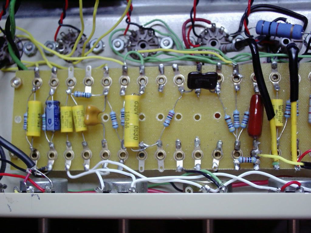
What is supposed to be going on there? I see from the plate of V1B, the yellow cap > resistor > brown (black?) cap > PI input. This isn't making sense to me. What am I missing? Also, tell me, what are the values for the cap>R>cap sequence that you are jumping over. (I don't want to rely on the color I see on my screen.)
At the bottom of the picture, opposite the brown cap, I think I see three soldered lugs, maybe two with black wires, but I can't see what's on the middle lug of that set of 3. What's going on there? Please explain.
Are you using someone else's layout or is this your own? Is there a layout drawing? If so, post that, too.
BTW, I use those yellow boards,too, and I understand that sometimes you've got to improvise a bit to make them work.
It looks like you've yanked the wires off the board from V2. Hard to tell how you had this arranged. Maybe too much gain to the PI? Missing coupling cap?
You may want to start again using the Liverpool schematic, just omit the two outside power tubes.
Yes, I did yank the v2 wires from the board, and that gap in the middle of the board is where I removed the blocking cap resistor and dropping resistor. That mess there now is just tacked in to see if it would improve the situation. Its just strange that running straight from v1b plate to the p.i. works so well and any attempt to insert a cap or resistor between these 2 pointa brings back the hum and breakup. If I can't figure this out by Sat. I guess I will try a Liverpool, but I wanted to try something different. Well, this is different all right...
From the plate of second half of V1, you need a coupling cap and a grid leak resistor referenced to ground into the grid of V2. From the plate of V2 you need a coupling cap to the 1M grid leak on the PI.
I don't understand why you've got Plate>C>R>C>Grid, and it looks like the required ground reference is omitted.
V2 has been removed in an effort to troubleshoot the amp. It goes directly from v1a to the tone/volume pots, then to v1b. From there it goes straight from the plate resistor on v1b to the p.i . Any attemp to add blocking caps, dropping resistors or anything else adds hum and broken up sound. Why 250v from the plate of v1b to the p.i makes a stone quiet, nice sounding amp is beyond me. The 2nd pic shows a cap and resistor that I tacked in after removing the real circuits 2nd stage, just to re-verify that any attempt to add components, ruins the amp. I,m lost on this one.
 768]http://i212.photobucket.com/albums/cc29 ... 600012.jpg[/img][/img][IMG
