Impedance / Turns Ratio Question

General discussion area for tube amps.

Moderators: pompeiisneaks, Colossal

User avatar
bepone
Posts: 1669
Joined: Mon Mar 09, 2009 4:22 pm
Location: Croatia
Contact:

Re: Impedance / Turns Ratio Question

Post by bepone »

dorrisant wrote: Wed Sep 14, 2022 2:39 am Sluckey, I understand, no worries and thanks for that. But I'm not sure what the output impedance should be for this device. Therefore I am not sure what impedance ratio to look for on any data sheet. Sorry if I'm dense sometimes, rest assured it isn't most of the time. :wink:

Is it true that if i knew the device's target impedance along with the turns ratio that I could derive the impedance ratio?
technically you can terminate with any resistor, and this became your load impedance.. but this will be transferred to other side (mic if i understood) so you can create some distorsions or affect the freq. response. load it with 100k for the start.
i dont know which preamp are you have, but try to check one really good, REDD47 mic preamp, which has input step up transformer and you can see the compensation and resistor values which can give you some starting points. after you can fine tune.
https://www.tubecad.com/2020/06/blog0506.htm
https://www.tubecad.com/2020/06/16/EMI% ... lifier.png
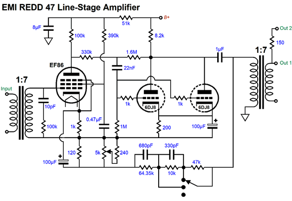
wpaulvogel
Posts: 448
Joined: Wed Jan 23, 2019 3:11 am
Location: Leesburg Georgia
Contact:

Re: Impedance / Turns Ratio Question

Post by wpaulvogel »

Audio transformer turns ratios are always given. 4K @ 8 ohms is the impedance ratio and that’s the turns ratio with a little math. They don’t tell you the actual number of turns of wire or the wire gauge and they don’t tell you the winding geometry. That’s the “secret stuff”.
R.G.
Posts: 1579
Joined: Tue Dec 02, 2014 9:01 pm

Re: Impedance / Turns Ratio Question

Post by R.G. »

For an audio transformer:
Turns ratio = voltage ratio when unloaded. "Unloaded" is required to keep I * R losses from messing with the measurements. Unloaded also means the wire resistances are not a factor.

As stated before, measure voltage ratio, you know turns ratio, although not absolute number of turns.

Impedance ratio = turns ratio squared, and turns ratio/voltage ratio = square root of impedance ratio. (note that makers of xfmrs often fudge the impedance ratio; it's not a precision datasheet number)

These have to be measured in the middle of the transformer's pass band to avoid response funnies fouling up the measurements. So for small audio transformers, use something like 1kHz for a test frequency, as nearly all of them will do 300Hz to 3kHz, even small coupling devices.

So (1) isolate all of the transformer connections (2) Apply a mid-range frequency to a winding. (3) measure the voltages on all windings. Voltage ratio are equal to turns raios. (4) square those voltage ratios; this is the impedance ratio.

Carefully designed transformers will some times confuse the issue with DCR. The need to handle power, not just voltage, means that the DC winding resistances will naturally home in on being similar to the impedance ratio.
"It's not what we don't know that gets us in trouble. It's what we know for sure that just ain't so"
Mark Twain
User avatar
dorrisant
Posts: 2790
Joined: Tue Sep 21, 2010 1:27 pm
Location: Somewhere between a river and a cornfield
Contact:

Re: Impedance / Turns Ratio Question

Post by dorrisant »

Thanks for the answers guys.

If I'm simulating a mic, let's just say an SM57 for sake of argument, and it needs to be 200mW, what primary impedance would I look for? I am assuming this will give me the primary impedance to work backwards from, since this will be used as a step down TX.

I have a plaque in the shop... I need to read it sometimes. It says:

"If you're happy and you know it, overthink.
If you're happy and you know it, overthink.
If you're happy and you know it, then your brain will surely blow it.
If you're happy and you know it, overthink."

:wink:
"Education is what you're left with after you have forgotten what you have learned" - Enzo
Post Reply