Yeah, that's from a different series. Lots of people pull those off. Mine is an 81-87 wagon-style, and in Kalif, smog-police will get you if it's non-operational.
I'm trying to see if there's a way to repair (or test) these, rather than find a replacement, because almost all the replacements out there, were pulled because they were bad.
If Toyota or aftermarket offered these, I would just buy one ....
Last edited by Spike Strip on Sun Apr 21, 2013 11:04 pm, edited 1 time in total.
Tillydog wrote:Why do you think it's the board and not a sensor, wiring, corrosion, etc...?
It's difficult to see from the picture, but is that a cracked track by the red arrow below?
It might be worth re-flowing all the connections in any case if you haven't got anything to lose :-/.
I've checked all sensors, wiring, done a complete diagnostics per the factory emissions service manual. Narrowed down to emissions board and these are known to fail.
The arrow in the above pic is just to some errant spec of solder, but sharp eye, nevertheless !
These control the various systems by "Grounding" the circuits (neg). The areas shaded in blue are the grounding circuits.
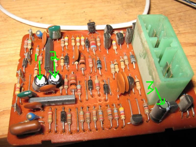
I might start with the easiest and most like to fail, those three electrolytic caps. They should be marked with their capacitance and voltage rating. Those caps are almost thirty years old. You may even be able to find replacements at Radio Shack.
Unsolder them and put in replacements being sure to observe polarity.
LeftyStrat wrote:I might start with the easiest and most like to fail, those three electrolytic caps. They should be marked with their capacitance and voltage rating. Those caps are almost thirty years old. You may even be able to find replacements at Radio Shack.
Unsolder them and put in replacements being sure to observe polarity.
Yes. In a guitar amp you're usually advised to replace them every ten years.
If you have a multimeter you can pull them out of the circuit and check for capacitance (if your meter has this function) and more importantly DC resistance, which if you get a reading, the cap is leaking and needs to be replaced.
Do one at a time. Very important. Take a sharpie and mark the hole that the band indicating the negative side is on. These are polarized and you need to make sure you make note of which side is positive and negative.
The cap should have some value like "10 uf" and a voltage rating, probably 25 volts.
You can order them from Mouser.com and they'll probably cost less than shipping. The mouser website can be daunting, but if you post the markings we can probably help you find them.
LeftyStrat wrote:You can order them from Mouser.com and they'll probably cost less than shipping. The mouser website can be daunting, but if you post the markings we can probably help you find them.
Again, thanks for the help, Lefty, with a noob ... Afterall, I'm a Biologist, not an Engineer!
Spike Strip wrote:
Again, thanks for the help, Lefty, with a noob ... Afterall, I'm a Biologist, not an Engineer!
That's even messier and fuzzier than analog electronics! I'm a programmer by trade. It's either on or off. Maybe you can explain to me someday whether a virus is considered a living creature.
I hope this is what is wrong. I realized probably the only place more inhospitable for electrolytics than inside a tube amp is inside an engine compartment. Well, except for where the NASA guys are sending things.
I think it would definitely be worth re-flowing some of those solder connections. I don't know if it's the lighting in the photos, but some of them look a little puckered, and possibly intermittent. That board has probably seen a lot of vibration, so hairline cracks in the solder around the component pins is a possibility.
Probably a 25 watt iron would be plenty, and use good flux. Don't cook the components or lift the traces off the PCB. Just keep the iron on there long enough to get the solder to re-flow.
It doesn't look like anything on the component side of the board was on fire, and no obvious blebs or cracks in the chips or transistors. But hard to say for sure.
A good re-flow sure couldn't hurt, as long as you don't use too much heat.

