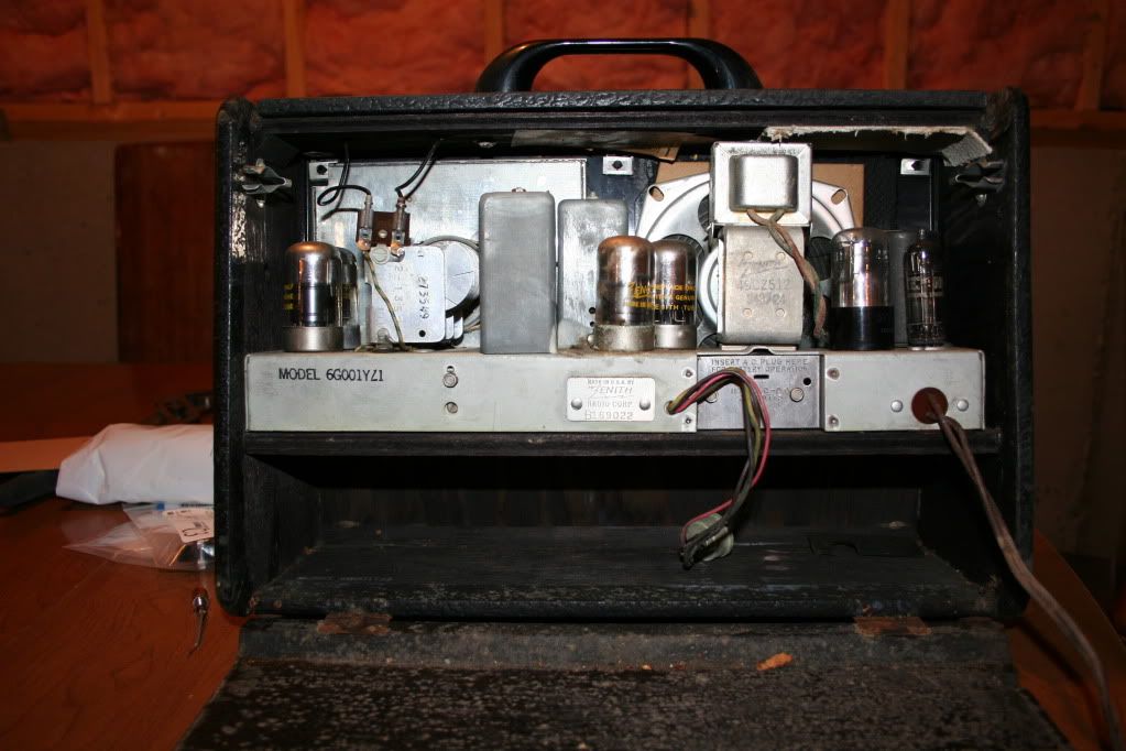
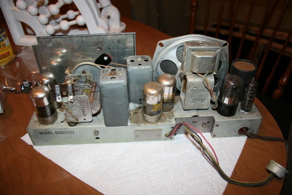
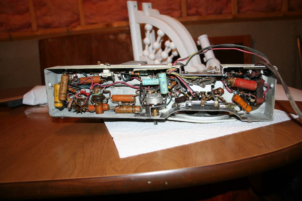
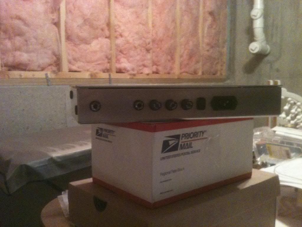
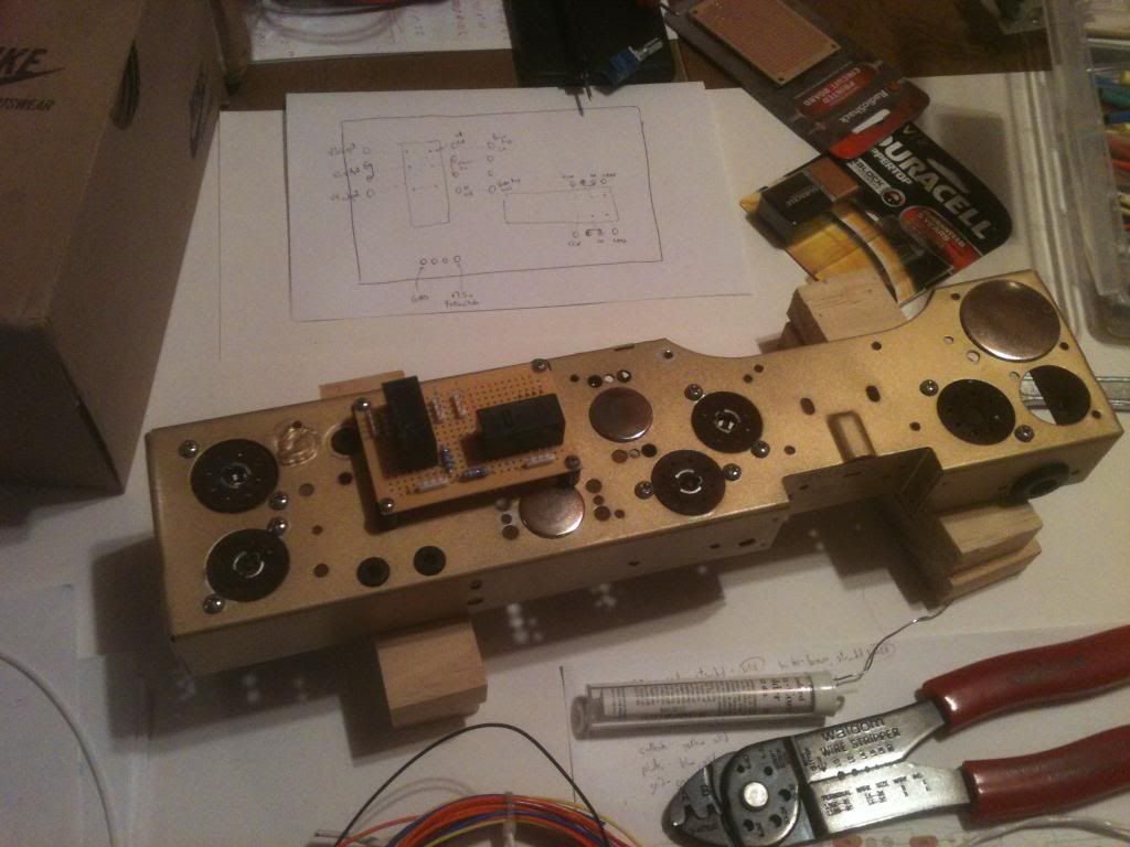
So I spent quite a bit of time trying to figure out how to make a high-gain amp out of this radio. This is a very silly project, these tubes are totally unsuited for the purpose and they pose a lot of challenges. The chassis is also unfit-for-purpose, with tubes at opposite ends, and nothing in the middle. The radio lacks an isolation transformer, but fortunately there's a battery compartment in the "briefcase" where I can put in a power transformer.
I've attached my schematic to this post, in PDF form. Acrobat has a "rotate" feature you may want to use. I did it in KiCAD using a symbol library I made up myself. Any oddities with symbols are probably my fault, and not KiCAD's.
You'll notice looking at the amp section, that there are no cathodes. The tubes in this radio are all directly heated cathodes, so the filaments in the power supply are the cathodes. This makes biasing a challenge. I used LED's to bias the cathodes, so current changes wouldn't change the filament voltage. The 1N4150 diode on V4 is the only tricky one, it's voltage drop varies slightly with current, but not by a lot, and it's close enough to .5 volts, which is what I wanted to bias that tube at.
Going over the stages of the amp one-by-one, I will explain my rationales for the circuit:
V1 - This is the staple of all guitar amplifiers, the heptode valve. It's a 1LA6 loctal pentagrid converter. The data sheet I downloaded was pretty laughable, with no graphs at all. I've only got a list of "typical use" voltages, so I set the thing up according to the data sheet's recommendations. Given that it uses similar voltages to the 1NL5 pentodes, I cut the plate amps in half from the recommendation, as that's roughly what I did when I drew load lines for the 1NL5's in triode mode. This is a lousy choice of tube for the first stage - it's got the highest voltage out of all the stages but one, so it's second in line on the power supply with the attendant ripple issues, and with all those grids it's microphonic. But, I don't know anything about the tube, and out of sheer perversity I don't want to move tubes and it's near where I want the input jack to be. So for these terrible reasons it shall be the first valve.
V2 - This is a 1NL5 pentode. I will be running it in triode mode. All it does is add more gain, per the load lines I drew I don't expect significant distortion. A relay will switch this stage through to the tone stack / power amp for clean tones. The data sheet is pretty sparse, there is no mutual characteristics graph, so I'm just keeping screen voltage equal to plate voltage.
V3 - This is the second 1NL5 pentode, also in triode mode. This should add a bit of asymmetric distortion. It's biased low so one side of the signal should get really squashed. Again, screen voltage is roughly equal to plate voltage.
V4 - Finally, an actual triode. Well, a diode/triode combo, really. This stage is just the triode portion. The data sheet for this one is also lousy - they've got the graphs, but the parts of the graph that are useful are down at the bottom where all the lines are squashed together. Why run up an axis to 1500 microamperes if typical usage is at 150? Jerks. Using this lousy graph I took a stab at a -0.5 bias, and V3 is going to send enough voltage that it will distort ridiculously no matter where I bias the thing anyhow.
Tone stack - Mildly tweaked Fender Brownface tonestack. I like it because it only has 2 knobs, and works well with high impedance inputs. I'm not wasting a tube on a cathode follower just to drive a tonestack. Even if I was so inclined, it would be weird to try with directly heated cathodes.
Power amp - This is a single-ended power amp using a 3Q5GT pentode. This tube is NOT loctal, so it comes out of the socket without any fuss. I disconnected the speaker and output transformer, the speaker looks like it's around 4 ohms, and the transformer is a 50:1 winding (measured using variac), so that's a 10k ohm load. If I don't want to exceed max dissipation, I'll need to keep it at 75 volts - which is what the original radio schematic was using. I'm biasing it at -4.5v using a nice bright LED, which is also how the original schematic had it biased (well they used a series of tube filaments to bias, but same effect). I then tossed in a 2k resistor onto the screen for safety since I'll be overdriving this thing, which was definitely not in the original circuit design. The data sheets once again lack a mutual characteristics graph, so I'm not 100% sure what the difference in screen voltage is going to do. Probably not much, it's not a big difference.
That's the pre and power amp. Now, on to the power supply. The radio I bought had been modified to use a 117Z3 rectifier instead of a 117Z6GT/G. The thing is, a 117Z3 is just a single diode. How you make a power supply using one diode, I don't know. I expect it didn't work. A smaller socket has been put in place for the 117Z3 so somebody went to a lot of effort. Whatever, these tubes are dirt cheap, so I'll order a 117Z6GT/G and a socket for it.
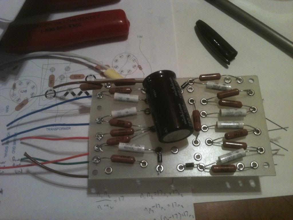
A problem with the 117Z6GT/G is that it lists a 40 uf filter capacitor in the data sheet. That's not very big. So I designed a pi filter, with one leg being 39 uf, and the next 1000uf, with a 750 ohm resistor in between. I really want the filter caps to be large to minimize the ripple going to V1, which is the second tube in the chain. But, I'm wondering if 750 ohms is enough to keep that 1000uf cap from smoking the rectifier. Maybe I should just toss the whole notion of a tube rectifier and stick with diodes.
Speaking of diodes, the transformer I've purchased is an Antek AN-05T120 (
http://www.antekinc.com/details.php?p=637). The radio didn't have a power transformer, so this will provide isolation and some low voltage DC. It doesn't have a center tap, so I will use a pair of diodes with the tube rectifier to form a bridge rectifier.
Low voltage for the filaments will be provided by a 2A 7.5V voltage regulator, so it will be clean. It's plenty of current for the last part of this schematic, which is the LED indicators.
The radio has a transparent Perspex arc in its face that shows the radio frequency. I will line up two rows of LED's behind the Perspex, and they will indicate the gain and volume. The gain and volume pots will be dual-gang, and the second half of each will drive a series of LM339 quad comparator IC's that compare the pot's value and turn on the appropriate LED's. Pointless, but it does something with that Perspex strip that would otherwise look stupid.
All comments are welcome, I'm sure there's stupid mistakes and bad ideas in this schematic, and I'd love to be corrected early.
You do not have the required permissions to view the files attached to this post.
 682]http://i234.photobucket.com/albums/ee25 ... _front.jpg[/img]

 768]
768]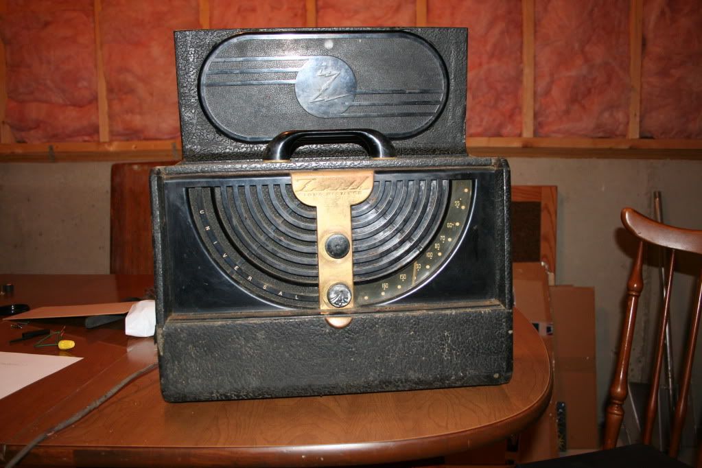