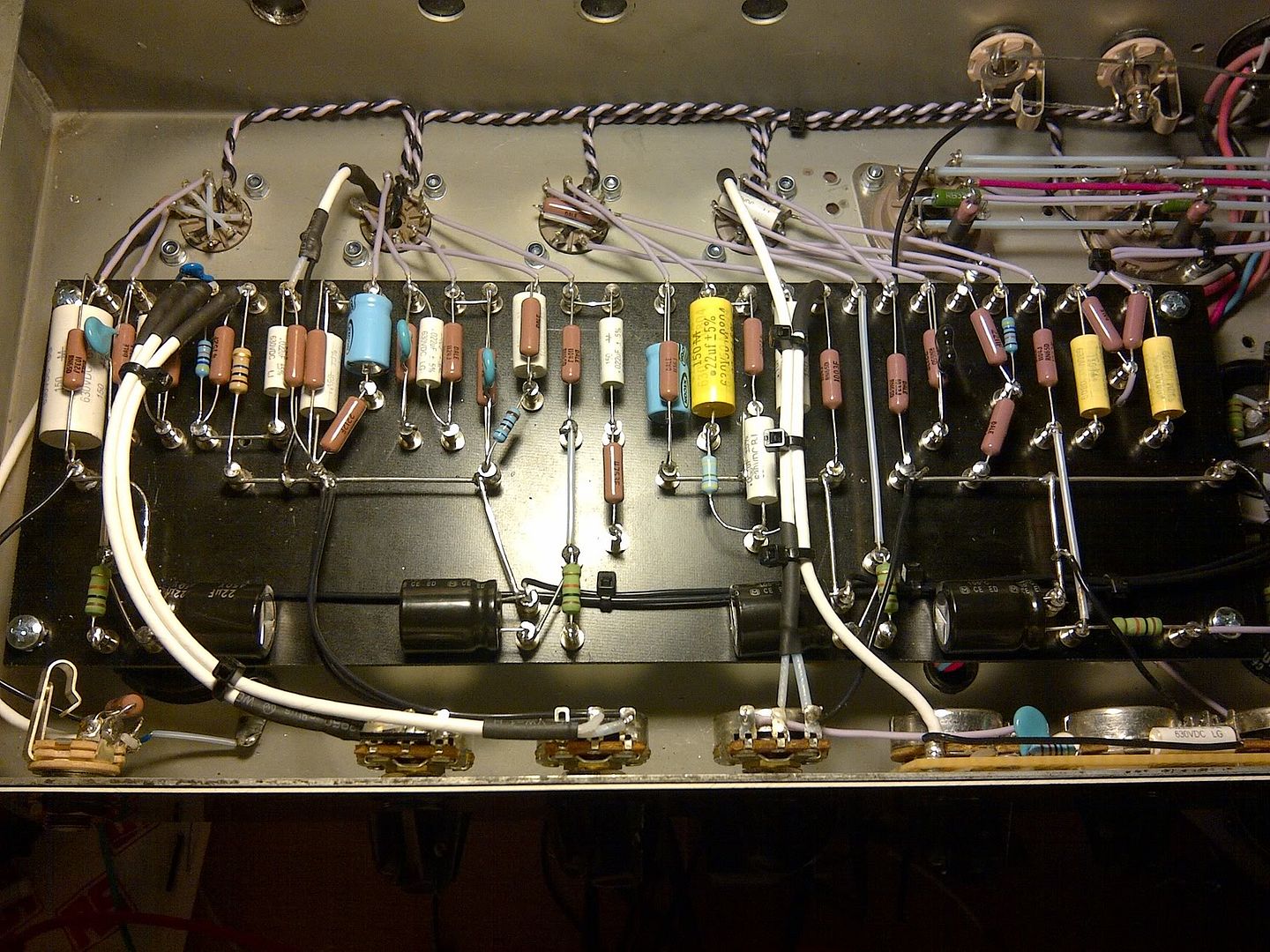
I've been working on a build. That's high gain again. It sounds good but suffers from some hum. It's in an old Laney AOR series II chassis and I'm using an in-line filtered IEC. 6A.
I've tried pulling tubes in order and poking things around.
I've gone for star/node ground as per merlins book....
Star is located by main filter caps.
DC heaters connect to star
Bias and Reference for elevated AC heaters goes to star
B+ CT goes to negative side of first filter stage, and that then goes to the star
octal pins 1 + 8 go to the negative side of the second filter stage and then to star.
Output jacks are grounded to the bottom of the cathode resistor of the stage taking the NFB.
The preamp is divided into 4 nodes, each going to the star.
The input jack is grounded to the bottom of the cathode resistor of the input stage, and has a 1000pf 1kV cap from directly to ground.
I'm pretty sure my grounding isn't that bad... however one thing I have noticed is if I run my finger along the edge of the back panel (the steel of the chassis) the hum decreases while I touch it. However If I touch the panel near the IEC I can still hear some hum but If I then run my finger slowly to the left along the edge of the chassis, the hum gently decreases and is totally gone when I get around the V2/V3 9pin sockets. Touch that area of the chassis (the back of the chassis on the opposite side of the IEC) seems to cut the hum down to almost zero.
this is what the chassis used to look like
http://i33.tinypic.com/ae0g90.jpg
and now
http://img.photobucket.com/albums/v174/ ... -00603.jpg
http://img.photobucket.com/albums/v174/ ... -00602.jpg
I'll be swapping the pots soon. hate the bourns after using them for this.
hum issue in my build
Moderators: pompeiisneaks, Colossal
hum issue in my build
Maximum volume equals maximum tone

Re: hum issue in my build
Wow that is a beautiful build.
In comparison, my latest looks like I threw components at a magnet, but it's as quiet as a churchyard until everything is dimed and the TS is lifted anyway.
All I can think is that the lead dress might need chopsticking around. Also check the pot grounds too. I isolated mine with shoulder washers.
You may just lose some neatness but gain some hush
Good luck
Re: hum issue in my build
Thank you so much for the kind words. It isn't perfect but it's my best so far.
I think I found the hum!
I added another shielded wire to the second grid on V2. That took a lot of the hum out.
I'm going to replace the original shielded wire on V2 as well, and get the shield as close as I can to the cores with going core to shield on me.
maaaaan! what an easy fix. been tearing my hair out!
Maximum volume equals maximum tone
Re: hum issue in my build
Pretty build, but sometimes having the wires all tied together in parallel can cause some bleed.
This might not help what is left of the hum but generally you want your preamp wires to come off the board and go straight down to the chassis floor which is the quietest place.
If you must cross wires, do so at a 90 degree angle.
Supposedly having the filter caps close to the stages is a good thing like you did.
I imagine if you had a scope you could pin point where the problem is.
The one thing that I do not like is the way you have the heater wire to pin 9.
Going across the socket like that is more noisy than looping the wire around the socket to the pin.
I prefer to wire the heaters overhead as I feel it is quieter and allows the back corner of the chassis to run other wires to the back panel.
Just my 2 centavos.
Tom
Don't let that smoke out!
Don't let that smoke out!
Re: hum issue in my build
Hey Structo (and others that have an opinion on heater wiring)
Having recently been chasing hum in one of my builds I read all I could about heater wiring and at Merlin's Valve Wizard site he says the exact opposite about pin 9 heater wiring - i.e. wire it straight across, not wrapped around the base. In my case changing it from wrapped to straight across the base of the tube had negligible effect but I'm curious what others have to say about the hum of one method vs the other.
Obviously Merlin seems to go against the grain vs most of the builds I see here..
"The common pre-amp valves (ECC83 / 12AX7 etc.) when run from a 6.3V supply, should be wired from one side only [see right], not by looping one heater wire all round the valve socket, which would create a hum loop and cause excessive interference noise (though many amp makers DO make this mistake and get away with it). The wire twisting must be kept very tight right up to the socket, where it matters most. Their pin arrangement is also deliberate, so that the main heater pins (4 and 5) can be orientated towards the chassis wall, allowing heater wires to be run along the wall away from any other sensitive signal wiring."
You do not have the required permissions to view the files attached to this post.

Re: hum issue in my build
Hmmm....heater wiring, now that's a debatable topic. Take what everyone says with a grain of salt. I know what works for me. I like them up in the air, like this. OK, I was too lazy to trim the excess between V4 and V5. I am concerned, in your build, you've got heater and signal wires mixing at the socket in ways that they shouldn't.
Take a look at socket wiring for plate, grid, and cathode. This is what Tom (Structo) is describing -- on the floor to the socket. If that one hadn't worked OK, there are a few things I would have reworked, especially the red B+ wires for V1 and V2, which I really don't like. This is an amateur level build. There are others here whose skill are way better than mine.
Anyway, although what you did is pretty, I think you have made some trouble for your build with your board to socket connections being stretched tight like that. There are many wires that cross, but not at right angles.
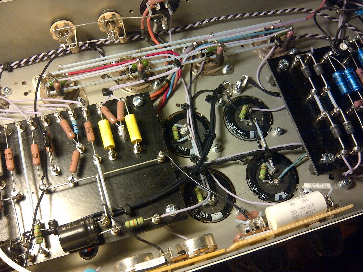
In your picture #602, there is a bundle of wire going under the socket wiring (BTW, nice job on those sockets V5-V8 ). I think maybe the zip tie wraps in one of the socket wires -- I wouldn't do that. I think I'd have created a hump to form a tunnel to the output selector switch(?) between V6 and V7 to keep the OT wires on the floor and as far away from other wires as I could.
I'm not seeing where you output jack ground goes, but am not fond of where it seems to be headed. I ground this with the first B+ filter cap ground.
I sometimes find there is magic mojo in amp building. "Rules" are broken, yet the amp works fine. What works in a low/ordinary gain amp, probably won't be forgiven in a high gain amp. As gain ramps up, lead dress and such become much more important.
Good luck with it.
Phil
Take a look at socket wiring for plate, grid, and cathode. This is what Tom (Structo) is describing -- on the floor to the socket. If that one hadn't worked OK, there are a few things I would have reworked, especially the red B+ wires for V1 and V2, which I really don't like. This is an amateur level build. There are others here whose skill are way better than mine.
Anyway, although what you did is pretty, I think you have made some trouble for your build with your board to socket connections being stretched tight like that. There are many wires that cross, but not at right angles.
In your picture #602, there is a bundle of wire going under the socket wiring (BTW, nice job on those sockets V5-V8 ). I think maybe the zip tie wraps in one of the socket wires -- I wouldn't do that. I think I'd have created a hump to form a tunnel to the output selector switch(?) between V6 and V7 to keep the OT wires on the floor and as far away from other wires as I could.
I'm not seeing where you output jack ground goes, but am not fond of where it seems to be headed. I ground this with the first B+ filter cap ground.
I sometimes find there is magic mojo in amp building. "Rules" are broken, yet the amp works fine. What works in a low/ordinary gain amp, probably won't be forgiven in a high gain amp. As gain ramps up, lead dress and such become much more important.
Good luck with it.
Phil
You do not have the required permissions to view the files attached to this post.
Re: hum issue in my build
The OT wires are running along the floor of the chassis and up to the switch. It's hard to make out in that photo. The OT primary goes the same way, along the floor. The OT secondary wires are slightly twisted together with a tie wrap on, there is no tie wrap on the primary. There is a tie wrap on the wires from the output coupling caps to the power tube grids.
nothing is actually running through, or tie wrapped into any of the wires running across V5 - V8. its kind of hard to see how things are spaced in real 3D in that photo.
The output jacks are grounded to the same point as the cathode resistor for the stage where the negative feedback is injected. I think that was the method laid out by Merlin and also on Randall Aikens tech pages. I have tried using a lock washer on the output jacks and grounding it to them to the chassis but that made no difference. i could easily try your method.
One thing I thought of, was the shields on the 3 wires running to the gain pots are grounded at the tab on the pot, then via a wire to the corresponding ground node. So, I assume noise would have to run from the wires by the V1 & V2, up to the gain pots, past the pot wipers and then back to the preamp board. When I change the pots, it feels like a good idea to ground the shields at the opposite end.
I also put my meter across one of those bourns pots. The least resistance I can get according to my meter is 3.5ohms. wiper to either outer lug. I checked a clarostat at that read 0.05ohms (which is the lowest my meter seems to go). That doesn't seem that ideal.
Maximum volume equals maximum tone
Re: hum issue in my build
In your "before" picture of the chassis, I like how the wires are routed to the preamp tubes.
They go straight down to the floor then to the tube pins.
But like Phil S said, sometimes you get lucky, other times not so much.
You need to pinpoint where the hum is getting into the circuit.
You can use a scope if you have one or a stethoscope and listening amp type thing to chase the hum down.
They go straight down to the floor then to the tube pins.
But like Phil S said, sometimes you get lucky, other times not so much.
You need to pinpoint where the hum is getting into the circuit.
You can use a scope if you have one or a stethoscope and listening amp type thing to chase the hum down.
Tom
Don't let that smoke out!
Don't let that smoke out!
Re: hum issue in my build
cool.
I can have a go at putting the plate and cathode wires on the bottom of the chassis, but I don't have much left of the shielded wire I use. Is it worth trying the plate and cathode wires first, then maybe looking at the shielded grid ones at a later date?
I actually bolted this amp back into the shell, which has foil across the base, and most of the hum has gone. I'm still going to work on it though. I'd like to reduce the noise floor as much as I can, so thanks for the pointers.
Maximum volume equals maximum tone
Re: hum issue in my build
You shouldn't need shielded wire from the board to sockets v1-v4. Just use good quality and properly rated for the voltage. I can't recall ever using shielded wire for what amounts to something between 2" and 5" of wire in that kind of location. Grids are the most sensitive. I'd do those first and I'd check the result after each individual wire replacement. If you shotgun the job, you will never learn where the problem was and it won't have nearly the same educational value.
Good point about the bottom cover. Make yourself a cheap tool. Cut some heavy cardboard a bit larger than the open side. Spread glue on it. Put some heavy duty kitchen foil on it and press it down so it sticks. I use a rag to apply the pressure as it doesn't bind against the foil. This is something you can keep at your bench that costs almost nothing and has very high value.
Good point about the bottom cover. Make yourself a cheap tool. Cut some heavy cardboard a bit larger than the open side. Spread glue on it. Put some heavy duty kitchen foil on it and press it down so it sticks. I use a rag to apply the pressure as it doesn't bind against the foil. This is something you can keep at your bench that costs almost nothing and has very high value.
Re: hum issue in my build
Yeah, we should have mentioned the bottom chassis shield as an important ingredient in a quiet amp.
There are just so many things that go into a good amplifier build.
Then again, you can look at some of the old "Grail" amps and scratch your head wondering how in the hell does that sound good?
One of the best pieces of advice I can give you is not to make too many changes in between playing the amp.
Make one change, try it, make another change, try it, etc.
If you make many changes then try it you won't know which one was good or bad.
Tom
Don't let that smoke out!
Don't let that smoke out!
Re: hum issue in my build
thanks for the tip about the board and foil. that something I didn't think of having.Phil_S wrote:You shouldn't need shielded wire from the board to sockets v1-v4. Just use good quality and properly rated for the voltage. I can't recall ever using shielded wire for what amounts to something between 2" and 5" of wire in that kind of location. Grids are the most sensitive. I'd do those first and I'd check the result after each individual wire replacement. If you shotgun the job, you will never learn where the problem was and it won't have nearly the same educational value.
Good point about the bottom cover. Make yourself a cheap tool. Cut some heavy cardboard a bit larger than the open side. Spread glue on it. Put some heavy duty kitchen foil on it and press it down so it sticks. I use a rag to apply the pressure as it doesn't bind against the foil. This is something you can keep at your bench that costs almost nothing and has very high value.
As for shielding wires, I've done it on a couple of grids, and like you say, played the amp after each change. I wouldn't shield any of the plate of cathode wires.
It's not my first build, but it is my best so far. So yeah, I agree about making changes one by one, giving it a go, and so on. I'm here to learn. That is the goal.
I ordered some better shielded wire, with a heavier stranded core. The shielded wire in my build has a pretty thin core and I'm worried about its reliability. I'm going to swap all the shielded wires, and with the new stuff, I'll be more comfortable about routing them certain ways.
Maximum volume equals maximum tone
Re: hum issue in my build
If that was my amp, I might consider routing the shielded from the pots under the board and looping back around on top of the board. Just a thought -- and it may not be practical, as I'm not sure what is under the board in the way of transformer wires entering the chassis. Good luck with this. I think you've got it under control.
Re: hum issue in my build
cool. I think I'll do the plates and cathode wires first, see how it sounds, then tackle the shielded wires. The original shielded teflon wire I used has a thin core and putting stressful bends in it close to the solder point seemed bad. the stuff I have coming is 20AWG stranded core, so it should be much more robust in comparison. The only issue going under the board, would be the wire from the MV pot to the PI driver running right across the choke wires. I'm going to make a foil board tomorrow, and at some point i'll link an updated photo with some wiring differences.Phil_S wrote:If that was my amp, I might consider routing the shielded from the pots under the board and looping back around on top of the board. Just a thought -- and it may not be practical, as I'm not sure what is under the board in the way of transformer wires entering the chassis. Good luck with this. I think you've got it under control.
Maximum volume equals maximum tone
Re: hum issue in my build
OK guys.
I did some experimenting while I'm waiting on some better pots/cable.
[img:800:600]http://img.photobucket.com/albums/v174/ ... -00634.jpg[/img]
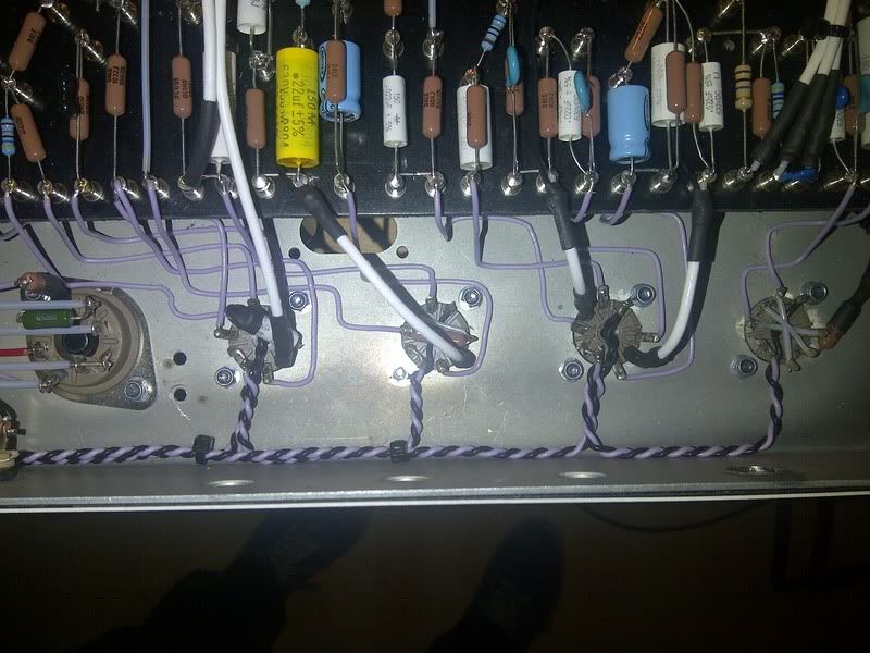
Here is the first thing I did. Flat on the chassis. It gets messy around the PI and its driver stage since there isn't a lot of space and all the wires are coming from a weird angle. Had to do some knitting. I didn't feel like this was that much quieter than the original 'direct-to-socket' style wiring I had done previously...
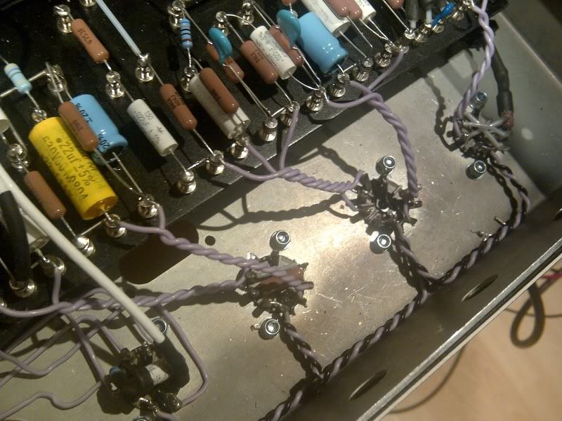
Then I decided why not have a go at this method out of merlins book.
[img:800:600]http://img.photobucket.com/albums/v174/ ... -00636.jpg[/img]
I've been interested in this idea but never dared to try it since it seems sort of counter intuitive. I think out of the original method, and the one previous, this actually seems to work. Notice that I ditched some of the shielded grids for this also, while I didn't in the other photo.
That may be unfair though I guess, since putting the grids down on the chassis would probably have helped.
Interesting though.
I did some experimenting while I'm waiting on some better pots/cable.
[img:800:600]http://img.photobucket.com/albums/v174/ ... -00634.jpg[/img]
Here is the first thing I did. Flat on the chassis. It gets messy around the PI and its driver stage since there isn't a lot of space and all the wires are coming from a weird angle. Had to do some knitting. I didn't feel like this was that much quieter than the original 'direct-to-socket' style wiring I had done previously...
Then I decided why not have a go at this method out of merlins book.
[img:800:600]http://img.photobucket.com/albums/v174/ ... -00636.jpg[/img]
I've been interested in this idea but never dared to try it since it seems sort of counter intuitive. I think out of the original method, and the one previous, this actually seems to work. Notice that I ditched some of the shielded grids for this also, while I didn't in the other photo.
That may be unfair though I guess, since putting the grids down on the chassis would probably have helped.
Interesting though.
Maximum volume equals maximum tone