
[IMG
 791]http://i260.photobucket.com/albums/ii9/ ... alues3.jpg[/img]
[IMG
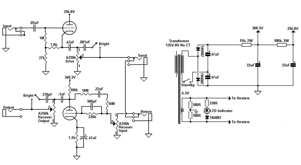
 563]http://i260.photobucket.com/albums/ii9/ ... atic-1.jpg[/img]
Moderators: pompeiisneaks, Colossal
791]http://i260.photobucket.com/albums/ii9/ ... alues3.jpg[/img]563]http://i260.photobucket.com/albums/ii9/ ... atic-1.jpg[/img]
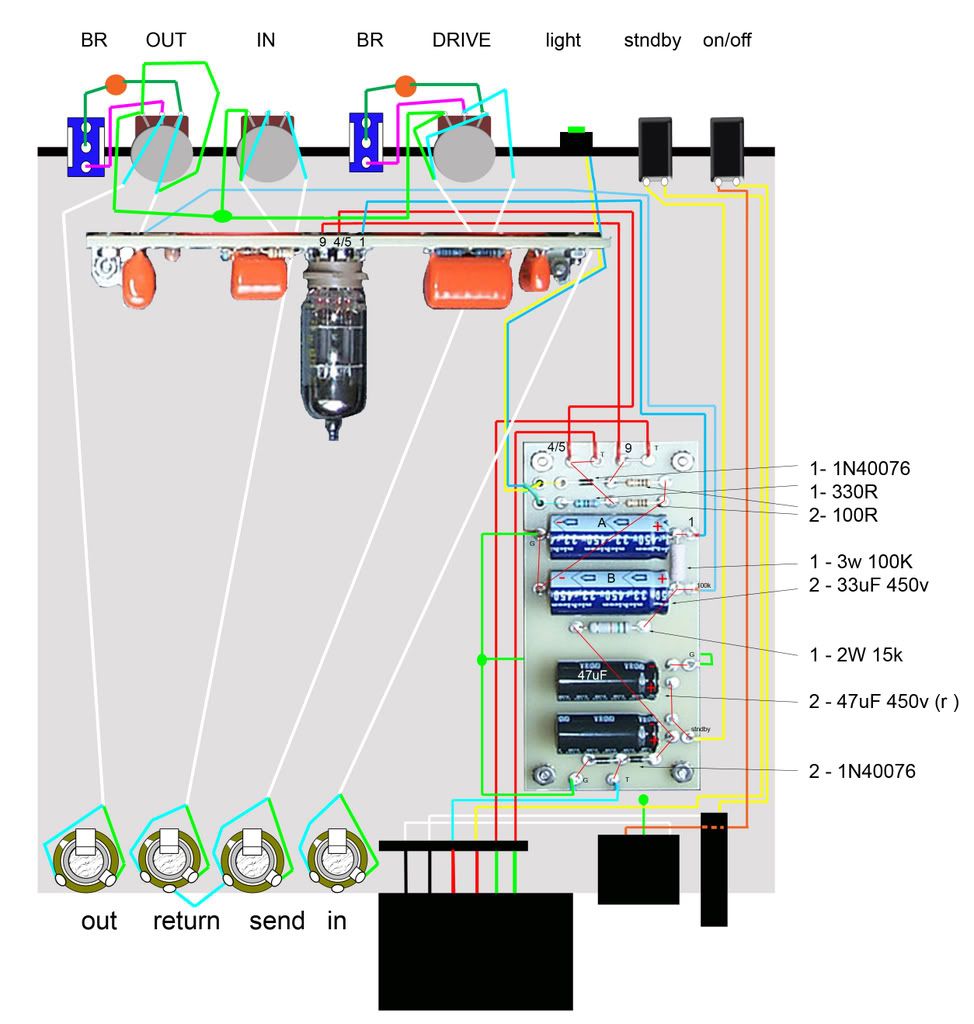
The 100k can be any type and 1 watt is adequate.angelodp wrote:Is the 3w100k a Vishay Dale
How about the 330R are they Metal Oxide ?
The 47uF what voltage please? is it 450v ?
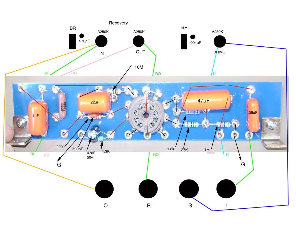
[IMG:400:300]http://i260.photobucket.com/albums/ii9/ ... uesjpg.jpg[/img]
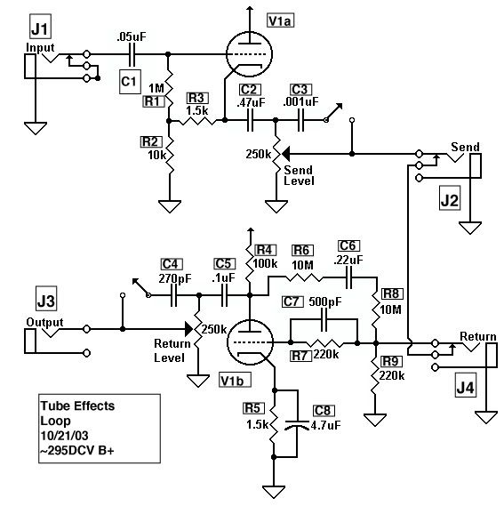
I may be mistaken, but isn't the cathode cap on the return triode supposed to be 4.7uF? (At least that's what I've been using in my loops.)angelodp wrote:Ok I think this is good to go know.
Thanks
[IMG791]http://i260.photobucket.com/albums/ii9/ ... alues4.jpg[/img]
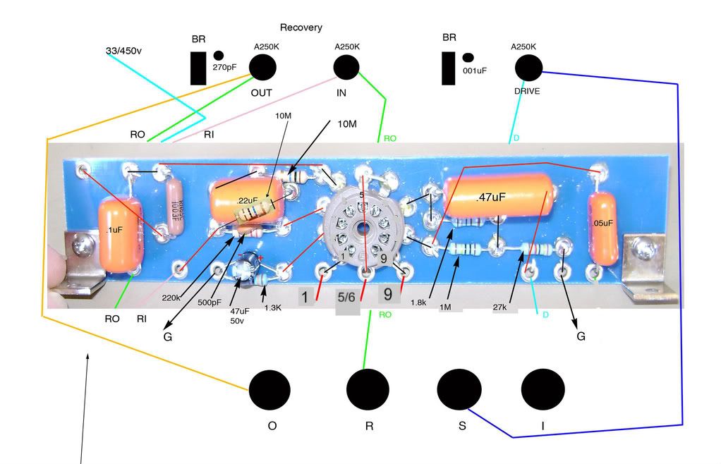
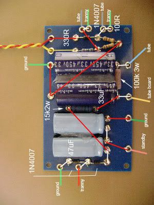
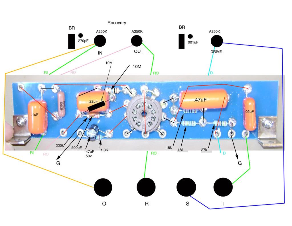
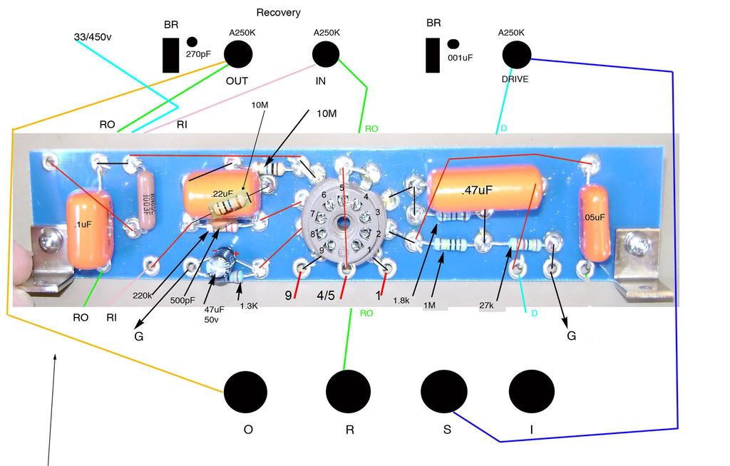
563]http://i260.photobucket.com/albums/ii9/ ... atic-1.jpg[/img]654]http://i260.photobucket.com/albums/ii9/ ... e_pins.jpg[/img]This is what I can tell you, based on many pictures of different Dumbleators. :angelodp wrote:There are two ( maybe more ) schematics that i have one shows the
1.5k 4.7uF pair the other shows 1.3k 47uF
I sure would like to know which one is the correct way to go. Look at the schematic above is it a typo??


