
Very nice work it will be fun to see you get his completed in the near future.
Mark
ODS in Progress
Moderators: pompeiisneaks, Colossal
Re: ODS in Progress
You may be going a little long on the tube wires.
Watch the grid wires as they will be sensitive to other wires around them.
The OT secondaries are best twisted and kept away as much as possible from other wires.
Some don't like to twist the black with the rest but I haven't noticed anything from it.
Watch the grid wires as they will be sensitive to other wires around them.
The OT secondaries are best twisted and kept away as much as possible from other wires.
Some don't like to twist the black with the rest but I haven't noticed anything from it.
Tom
Don't let that smoke out!
Don't let that smoke out!

Re: ODS in Progress
^I haven't installed the OT yet. I always test and braid my secondaries though.
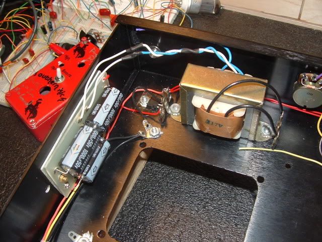
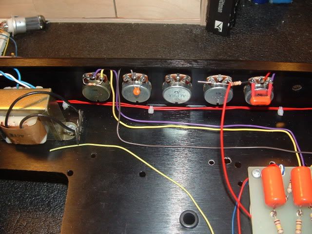
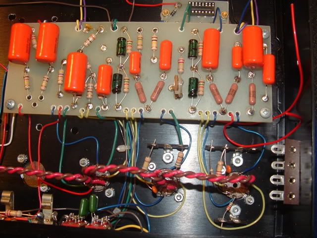
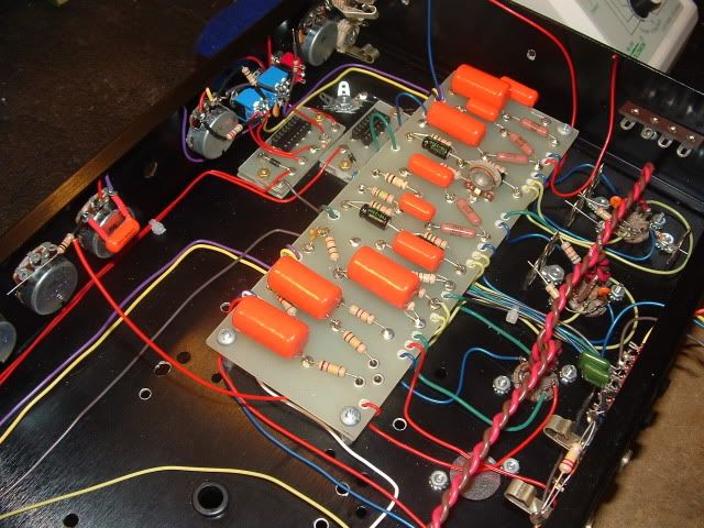
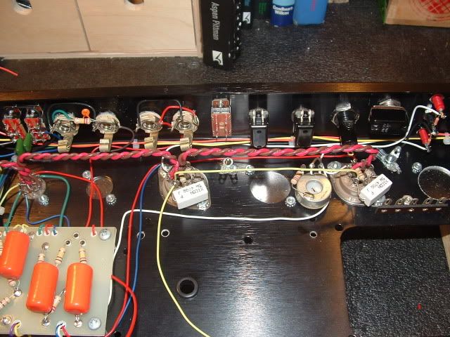
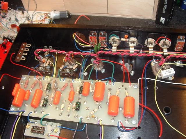
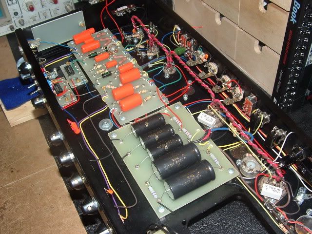
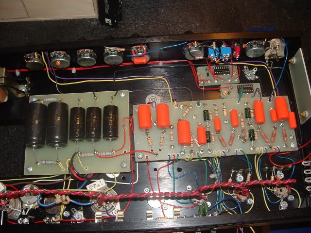
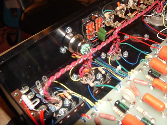
Did a bit more work. Wired up V1 and added the relay boards, also wired them up. Wired up and test the voltage doubled which powers the relays. It works perfectly when tested under load, gives a steady 12V DC. Also wired bias jacks and power tubes. The mini switches and control pots are also being wired.
[IMG:640:480]http://img.photobucket.com/albums/v610/ ... iring1.jpg[/img]
[IMG:640:480]http://img.photobucket.com/albums/v610/ ... iring2.jpg[/img]
[IMG:640:480]http://img.photobucket.com/albums/v610/ ... iring3.jpg[/img]
[IMG:640:480]http://img.photobucket.com/albums/v610/ ... iring4.jpg[/img]
[IMG:640:480]http://img.photobucket.com/albums/v610/ ... iring5.jpg[/img]
[IMG:640:480]http://img.photobucket.com/albums/v610/ ... iring6.jpg[/img]
[IMG:640:480]http://img.photobucket.com/albums/v610/ ... iring7.jpg[/img]
[IMG:640:480]http://img.photobucket.com/albums/v610/ ... iring8.jpg[/img]

Re: ODS in Progress
Work so nice it's boring  Come on make some mistakes so we can nitpick
Former owner of Music Mechanix
www.RedPlateAmps.com
www.RedPlateAmps.com
Re: ODS in Progress
Thanks! So far I am feeling pretty good about the build. I did a ton of reading and research before the build so I feel I have a better sense of what I am doing. Rob Livesey's Dumble page has also been a ton of help for lead dress ideas and just general stuff on how HAD wired his amps.
I think I found three small errors maybe in the layout for #124.
-The input grid resistor does not correspond to the schematic.
-On the PAB relay the schem notes two contacts are NC. On the layout it looks only one contact is NC.
-The volume posts wiper says V1-7 it should say V1-2. It does have to go through a filter though before reaching pin 2.
Re: ODS in Progress
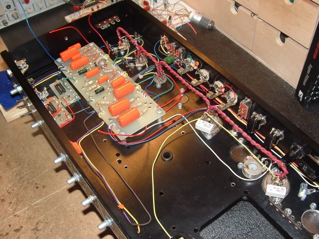
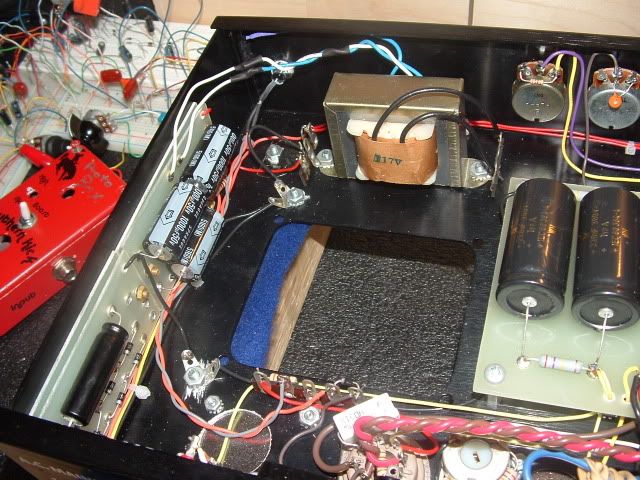
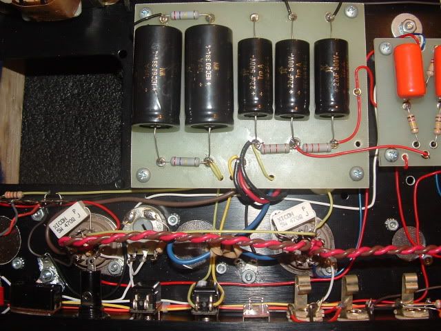
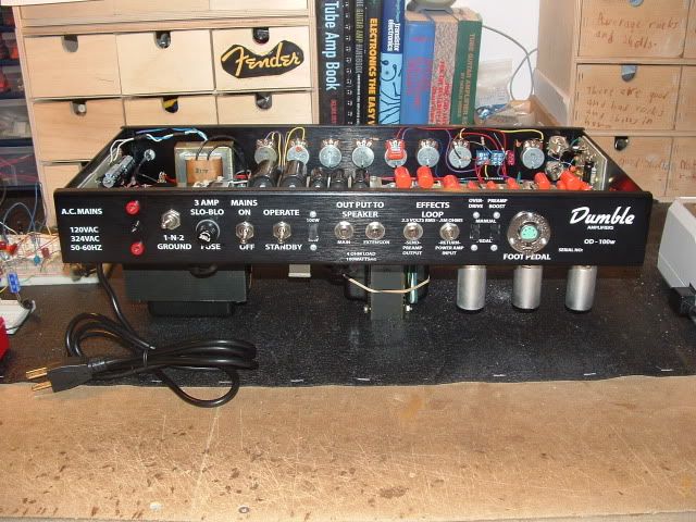
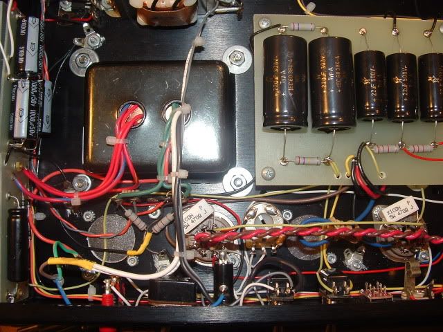
Did some more work this afternoon. Right now I am about as far as I can go with this build. I still need to order some more parts to finish it (PT, trimmers, a pot, footswitch jack and other random shit).
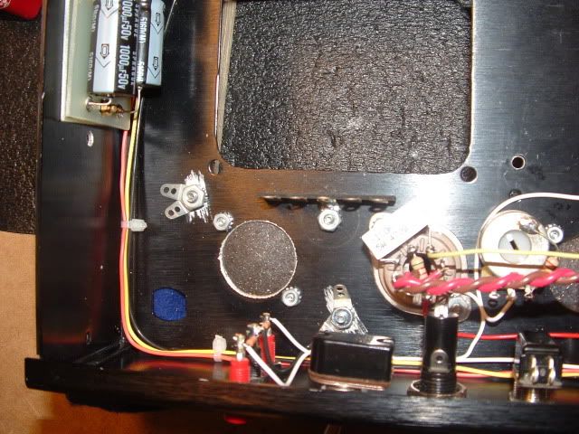
Right now the power supply and the OT's leads are a bit loose, leads to a bit messy look. It is just like this because the dropping string needs to be adjusted according to the PT and also because I am not sure if the OT is in phase. I might need to reverse the OTs leads, the NFB could make the amp into an oscillating mess.
[IMG:640:480]http://img.photobucket.com/albums/v610/ ... DSPro1.jpg[/img]
[IMG:640:480]http://img.photobucket.com/albums/v610/ ... DSPro2.jpg[/img]
[IMG:640:480]http://img.photobucket.com/albums/v610/ ... DSPro3.jpg[/img]
[IMG:640:480]http://img.photobucket.com/albums/v610/ ... DSPro4.jpg[/img]
[IMG:640:480]http://img.photobucket.com/albums/v610/ ... DSPro5.jpg[/img]
[IMG:640:480]http://img.photobucket.com/albums/v610/ ... DSPro6.jpg[/img]
Re: ODS in Progress
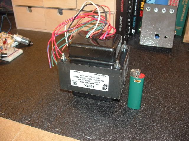
I got my transformer in today, PT that is. I have been told the transformer's shield wire goes with the AC main's ground. Is this where I should put it?
Also regarding the heater CT. Can I ground the resistor in the middle lug of the 5pin terminal strip near the PT? Or would it be better for it to go at ground point 2?
Also regarding the heater CT. Can I ground the resistor in the middle lug of the 5pin terminal strip near the PT? Or would it be better for it to go at ground point 2?
Re: ODS in Progress
You can ground the Heaters at the same location as the B+ center tap. I usually ground the PT there too but I guess it makes sense to ground it with the AC ground. I don't think it will make any difference in the noise floor. FWIW a "real" one used balancing resistors on the heaters and grounded them between the tubes and the rear wall.
Former owner of Music Mechanix
www.RedPlateAmps.com
www.RedPlateAmps.com
Re: ODS in Progress
Ya I am using the resistors for the CT. So you suggest grounding them with the PT CT then?
Re: ODS in Progress
Might as well do it like this then:
You do not have the required permissions to view the files attached to this post.
Former owner of Music Mechanix
www.RedPlateAmps.com
www.RedPlateAmps.com
Re: ODS in Progress
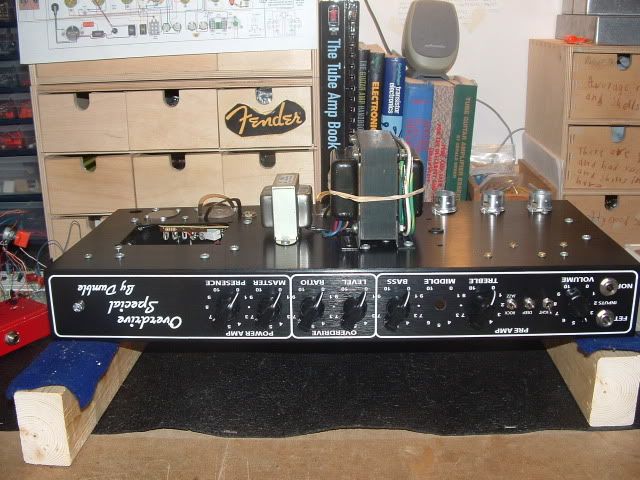
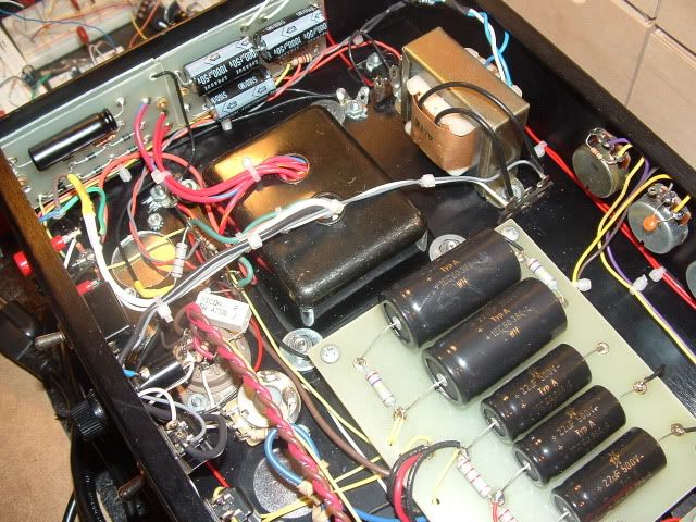
Got the power transformer yesterday, it's a beast.
[IMG:640:480]http://img.photobucket.com/albums/v610/ ... /ODSPT.jpg[/img]
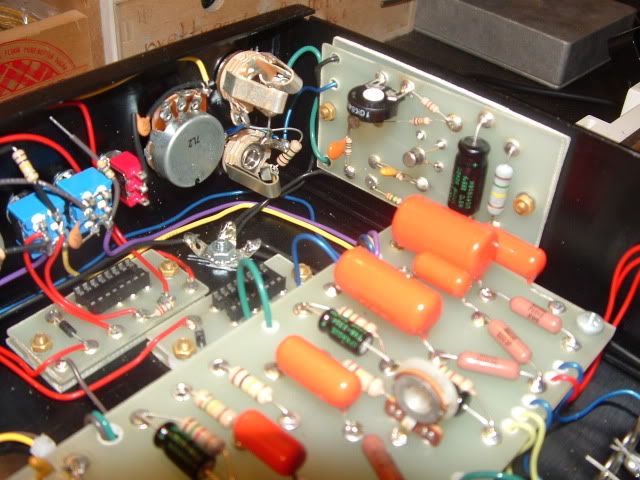
FET board installed and input jacks wired
[IMG:640:480]http://img.photobucket.com/albums/v610/ ... ETTrim.jpg[/img]
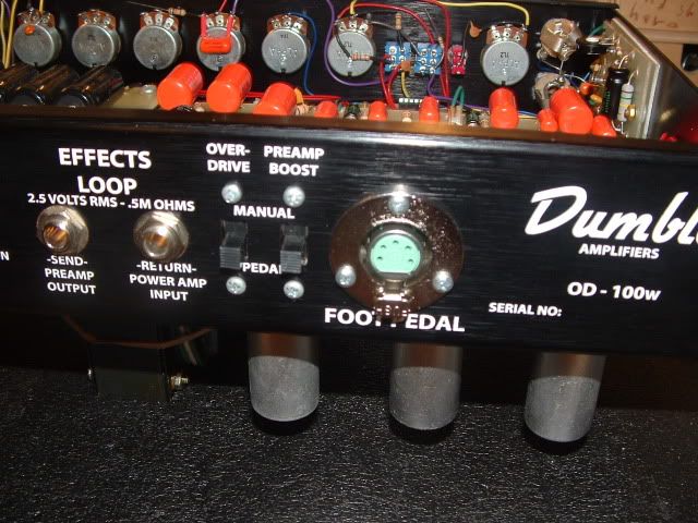
DIN jack installed and wired
[IMG:640:480]http://img.photobucket.com/albums/v610/ ... DINOut.jpg[/img]
[IMG:640:480]http://img.photobucket.com/albums/v610/ ... SDINIn.jpg[/img]
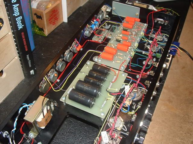
Power transformer installed
[IMG:640:480]http://img.photobucket.com/albums/v610/ ... talled.jpg[/img]
[IMG:640:480]http://img.photobucket.com/albums/v610/ ... TWire2.jpg[/img]
[IMG:640:480]http://img.photobucket.com/albums/v610/ ... PTWire.jpg[/img]
Going to install ground buss and add the coax tonight. Tomorrow will test it and go through the startup procedures.
[IMG:640:480]http://img.photobucket.com/albums/v610/ ... /ODSPT.jpg[/img]
FET board installed and input jacks wired
[IMG:640:480]http://img.photobucket.com/albums/v610/ ... ETTrim.jpg[/img]
DIN jack installed and wired
[IMG:640:480]http://img.photobucket.com/albums/v610/ ... DINOut.jpg[/img]
[IMG:640:480]http://img.photobucket.com/albums/v610/ ... SDINIn.jpg[/img]
Power transformer installed
[IMG:640:480]http://img.photobucket.com/albums/v610/ ... talled.jpg[/img]
[IMG:640:480]http://img.photobucket.com/albums/v610/ ... TWire2.jpg[/img]
[IMG:640:480]http://img.photobucket.com/albums/v610/ ... PTWire.jpg[/img]
Going to install ground buss and add the coax tonight. Tomorrow will test it and go through the startup procedures.

Re: ODS in Progress
Good luck with the start up! Now the fun begins. 
"Let's face it, the non HRMs are easier to play, there, I've said it." - Gil Ayan... AND HE"S IN GOOD COMPANY!
Black chassis' availble: http://cepedals.com/Dumble-Style-Chassis.html
Black chassis' availble: http://cepedals.com/Dumble-Style-Chassis.html

Re: ODS in Progress
Nice parts collection, but, does it sound good?
Re: ODS in Progress
Ok so after some initial PSU issues the build is passing sound.
I have found a few small issues and fixed them. The output is still quite low though.
The OD sounds almost the same as the clean and the PAB does nothing. So I am pretty sure the relay wiring is where to check next.
Here is what I am thinking...
I wired up the two little relay boards per the Ceriatone layout. I wired up the DPDT switches and DIN jack on the back per the 124 layout. I think my issues lies at the DIN jack/switches. Should I change to the Ceriatone style of wiring them up? The 124 and Ceriatone relay boards are not the same so I think this is my issue.
Re: ODS in Progress
Ok so I got the OD working. Seems I swapped the wires going to the 100K and 150K resistors. The OD is definitely noticeable now.
The PAB still isn't working and I dont hear the relay clicking. The output doesn't seem low but it doesn't feel like 50W. Ill have to keep working on it...
The PAB still isn't working and I dont hear the relay clicking. The output doesn't seem low but it doesn't feel like 50W. Ill have to keep working on it...