Charlie Wilson wrote: ↑Tue Jun 10, 2014 5:32 pm
Hello,
I watched the Kenny Wayne Sheppard video and I bet his amp is very similar to the circuit we are exploring here. As I stated before the amp runs pretty hot. I looked at my notes and I think it was running at about 17 watts per power tube (use JJs!). I was not concerned with output wattage, so my solution, rather than bias it cooler ( I don't like the sound of tweed deluxe with a cathode resistor higher than 250 ohms) was to drop the voltages to the power tubes( zener diodes and 5Y3) and then play with the dropping string to get the clarity back the phase invertor and preamp(I built a replica). I like the sound of tweed deluxes with 350v on the plates of the power tubes. I know this kind of defeats the idea of what Dumble was trying to do but it still made for a nice sounding amp ...
I was particularly interested in your build showing lower voltages than the original - cos these high-voltages spec'd transformers are not common on my side of the Ocean - but didn't made the connection...
This should explain why your build doesn't have this headroom++
(roughly speaking)
fred.violleau wrote: ↑Thu May 28, 2020 12:13 pm
@Marcus, Martin's numbers match exactly what I did.
I did use the 680k resistor. My previous build has a Tweedle Dee bright channel as channel 1. It puts out way too much signal to feed the loop FX without overdriving, so I had to tame it down with a trimmer sending part of that signal to the ground. Hence I was not surprised when I saw it on Rob's schematic
If you added a 470k resistor on the PI entrance, it should act as MV already, so you don't need an extra one. Volume control of each channel are adding More volume, but with a MV then these act as gain controls, and MV act as it should. I will try and record something quick at noon today so you can hear how ferocious this beast can growl
I think you are almost there Marcus, a few solder joints away from serendipity !
Fred.
Martin and Fred thanks.....Oh Lordy Lordy.......WOW....amazing......really is superb now. I think I have BLuesmaster values on my 1st channel so 2.2k/5uF and a 220k plate resistor. I have a switchable Sozo 0.0047uF 'bass' reducing cap on that channel as well.
It's a really versatile amp now. i have added a line out so i can feed a 100% wet FX for a wet dry set up. I'm thinking about the FX loop though as it would be better if I was only using 1 amp.
Could one of you tell me how to wire the loop in now it has this cascading switch?
Glad you like it Marcus, it really puts the amp into different territories, big, bold, and complex overdrive.
I like the FX loop, makes it a great grab'n'go amp.
EDIT
Very straightforward to add it :
1- Pin 2 (signal out) of the switch feeds the FX OUT signal jack of the loop (the one that grounds when nothing is plug into it)
2- FX SEND feeds V2A2
3- connect FX OUT signal (the one that groundswhen nothing is pluged in) with FX IN signal (so you get the signal from the preamp flowing on the RETURN and SEND jacks when no FX is connected) et voilà!
I grounded at the preamp star GND
And the MV helps a lot dialing the Power section distortion.
How's the grey Telecaster BTW ?
Fred.
Last edited by fred.violleau on Fri May 29, 2020 3:35 pm, edited 2 times in total.
Same here, my 1st channel has 2.2k/5uF and a 220k plate resistor. I removed the .022uf coupling caps and changed it for a .005uf Orange Drop 6PS 600v , reducing 'bass' on that channel as well. Works really well on its own to get a Benson type of clean sound with a slight break up when pushed. lovely!
Thanks Fred. That makes sense my switch is wired differently to yours as per Martins suggestion from your schematic, Martin has the resistor going between ins 7 and 9 and the jumper between 3 and 8 ......Seems to work so I'm not touching it!!!
I'll look into the PPIV master volume too and remove the 470k.
M
p.s. here's the Gray Guitars telecaster with a newly shaped neck some serious flame there
IMG_20200529_170748-01.jpg
IMG_20200529_170717-01.jpg
You do not have the required permissions to view the files attached to this post.
Thanks Martin, would love to hear the sound of your amps, your knowledge is such a gem, I wish I could lay an ear on your production!
You know that I would not have ventured here without your support ! You are a such generous resource I can't help but praise your interventions.
Side note : I did build the Martin Manning's SSS filters in a small Hammond pedal. It worked well although the controls were reversed (must have wired these the opposite way). I will try and build a thread with this small build, it was fun! I think it may be beneficial to have a 100W amp though to really get the depth of the changes in the sound. And I always seem to end up in one place : the one that pushes the amp and the tone to its full spectrum...
Yup great little amp, and I was wondering how it would act with a built in D-lator and the Step filters... It never ends
@Marcus, wow it is stunning, sure it sounds as great as it looks ! A builder from London, UK?
fred.violleau wrote: ↑Fri May 29, 2020 4:25 pm
You know that I would not have ventured here without your support ! You are a such generous resource I can't help but praise your interventions.
@Marcus, wow it is stunning, sure it sounds as great as it looks ! A builder from London, UK?
So I've removed the 470k and fitted the master volume. I've done the send and return loop too.
All good. Only thing I'd say is the master volume only seems to work in the first 1/4 of the travel then nothing much happens after that for the rest of the 3/4 of a turn. Would a linear pot work better? other than that it's all working well and the loop seems to work fine.
My Tweedle Dee now as more holes, knobs ,switches than it started with for sure I need another face plate and knobs as the master volume is squashed in there and there's no room for a chicken head knob!!
I'm curious about building either a combo or separate 2x10 cabinet for this amp now....... don't know why but I just have a gut feeling about it.
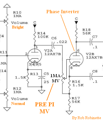
@chopsauce, interesting question! I did remove the 1 Meg resistor on my initial build, but I ended up putting it back. I remember the sound was not very loud without it, but I don't remember if I was connecting the MV button at the right place too... I ended putting it (the 1M resistor) back and connecting the MV as described on the schematics. It may refer more to "SweetSpot" PI grid stopper, but mine puts all the signal to ground when shutdown (I connected the 3 pin to ground).
SweetSpo.png
But my 1M pot is connected between the .02UF and the 1M resistor.
Thing is, if you go back to my voltages, my PI readings are way under what you find on CW's schematics. I asked if it was normal, but did not get an answer yet. So far it sounds really good, despite the fact that I may have to order a set of JJ 6V6s because it is getting really hot in that small head cab, and these old Sylvana tubes are starting to light in a blue color.
I am thinking of organizing the twin build upside down (in a head too) just to let the hot air flow up naturally and not heat the components too much. The PT iron is alos getting very hot after 1 hor or 2 of playing... So I may use a bigger iron on the second build to give it room to breathe.
Fred.
You do not have the required permissions to view the files attached to this post.