Making some progress. I'm about to drop the preamp board in.
Who has a 102 build? Any tips or tweaks that have really produced? I'm going to leave the shielded runs in for now since I can easily change them. I know I'm not gonna want to rip this board too much.
Metal Film cathode resistors?
#102 Started. Checking in
Moderators: pompeiisneaks, Colossal
-
amplifiednation
- Posts: 2091
- Joined: Sun Dec 26, 2010 6:19 pm
- Location: Boston
- Contact:
Re: #102 Started. Checking in
You do not have the required permissions to view the files attached to this post.
Amplified Nation
www.amplifiednation.com
@ampnation
www.amplifiednation.com
@ampnation
-
dcribbs1412
- Posts: 1386
- Joined: Wed Jun 11, 2008 6:56 pm
- Location: Arizona Desert
Re: #102 Started. Checking in
Looking good Taylor
your gonna have some great tone in no time...
I redid my 50 watt D'lite with 102 values
voltages/tubes matter..I did the deep switch and put the mid boost on a relay.I also put the LFNB on a on/off switch.Main thing I do is build it,play it
let it settle in for a while then decide what you like/dislike about it, and tweak from there...IMO of course.
Darin
Re: #102 Started. Checking in
Taylor
Take out those RN 65 grid resistors and put in some nice CF
Tony
Take out those RN 65 grid resistors and put in some nice CF
Tony
" The psychics on my bench is the same as Dumble'"
-
amplifiednation
- Posts: 2091
- Joined: Sun Dec 26, 2010 6:19 pm
- Location: Boston
- Contact:
Re: #102 Started. Checking in
Tony thanks, exactly what I was looking for. I'm still learning where and where not to put those RN65s! Thank you!talbany wrote:Taylor
Take out those RN 65 grid resistors and put in some nice CF
Tony
Darin, thanks for your comments as well. I will let the amp settle in for a bit. I'm trying to leave some room for tweaking but still get some solid mechanical connections. It is a slippery slope!
Amplified Nation
www.amplifiednation.com
@ampnation
www.amplifiednation.com
@ampnation
-
dcribbs1412
- Posts: 1386
- Joined: Wed Jun 11, 2008 6:56 pm
- Location: Arizona Desert
Re: #102 Started. Checking in
Taylor
noticed the 4.7 caps...cool matching orange
I bought some off ebay a while back...
I think they are Siemens not sure, but most of mine measured 6-7uf and above...not one was 4.7
not sure that my ears can tell a difference between 4.7 and 7.4,but I used
them on V1 on a 50 watt 102 style rebuild ...and I like the clean channel better with the Siemens than the 4.7 Spragues I had in it before. Of course there where other changes that probably affected the tone also...just an FYI
Darin
Re: #102 Started. Checking in
Not that it matters one iota but, when I built my 100w I changed things to 102 specs after those became known.
I ended up going with more of a 183 type preamp later on and have left it there.
But that is for tweaking later on.
Best thing is to get it built and put some hours on it, then decide.
I ended up going with more of a 183 type preamp later on and have left it there.
But that is for tweaking later on.
Best thing is to get it built and put some hours on it, then decide.
Tom
Don't let that smoke out!
Don't let that smoke out!
-
amplifiednation
- Posts: 2091
- Joined: Sun Dec 26, 2010 6:19 pm
- Location: Boston
- Contact:
Re: #102 Started. Checking in
I have plans to do a EL34 based Dumble if this one comes out the way it is supposed to!
I'm a bit of a Ford fan which made me want to do this build. Just wired up my green LED.
edit to throw a pic in here. just got the power tube sockets wired up.
i hope no one from work is watching this thread today! ahha
those heater ct resistors look a little weird but i think they'll do ok there. i wish i brought some more color into this section. at least the grid leads are blue and green
You do not have the required permissions to view the files attached to this post.
Amplified Nation
www.amplifiednation.com
@ampnation
www.amplifiednation.com
@ampnation
Re: #102 Started. Checking in
Yes, my amp is still 6L6 but I could probably run EL34's if I wanted to.
Really the differences between 102 and 183 aren't that big other than the power amp.
The Ford amp has a 2.2uF presence cap.
The Tag amp has 250K OD pots and small snubbers on V2.
When I wired the center tap resistors, I went from pin 2 on V5 and pin 7 on V6 to the ground lug that the black test point goes to.
The way you have it will work fine.
Tom
Don't let that smoke out!
Don't let that smoke out!
-
amplifiednation
- Posts: 2091
- Joined: Sun Dec 26, 2010 6:19 pm
- Location: Boston
- Contact:
Re: #102 Started. Checking in
I jumpered v4/v5 and moved the 100r ct resistor, i had it on the wrong lug (thanks t wilcox).
i don't have a 2.2uf, so it's gonna be a 1uf presence cap for now!
i don't have a 2.2uf, so it's gonna be a 1uf presence cap for now!
Amplified Nation
www.amplifiednation.com
@ampnation
www.amplifiednation.com
@ampnation
-
dcribbs1412
- Posts: 1386
- Joined: Wed Jun 11, 2008 6:56 pm
- Location: Arizona Desert
Re: #102 Started. Checking in
Are you jumping pin 1 and pin 8 on V4 and V5...
V6 and V7 looked tied...maybe just my eyes
V6 and V7 looked tied...maybe just my eyes
-
amplifiednation
- Posts: 2091
- Joined: Sun Dec 26, 2010 6:19 pm
- Location: Boston
- Contact:
Re: #102 Started. Checking in
I ran out of solder, got some questionable stuff at the local hardware store. It doesn't seem to bond well and has some nasty brown in it. That is flux right? I think I'm gonna get some different solder before I continue, we'll see if I can hold off.
[IMG 768]http://i817.photobucket.com/albums/zz97 ... wiring.jpg[/img]
[IMG
 768]http://i817.photobucket.com/albums/zz97 ... wiring.jpg[/img]
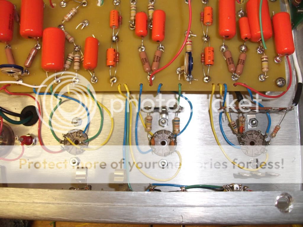
Amplified Nation
www.amplifiednation.com
@ampnation
www.amplifiednation.com
@ampnation
Re: #102 Started. Checking in
Take care when you solder the eyelets.
You can feed so much solder that it will start dropping out the bottom of the eyelet.
You don't need to raise the solder too much above the eyelet for a good joint.
Looks like you probably used rosin core 60/40 solder, hopefully.
The hardware stores also carry acid core solder which is a big no, no in electronics.
Also they carry no lead solder which is crap.
I like using 63/37 eutectic solder because it solidifies instantly when it cools with less chance of a cold joint.
Tom
Don't let that smoke out!
Don't let that smoke out!
Re: #102 Started. Checking in
Taylor
Looks good but what's up with the 100k slope and .047 mid cap? (classic stack) #102 was a standard Skyliner stack..If you are looking for the classic RF tone you have to go straight skyliner..
Tony
Looks good but what's up with the 100k slope and .047 mid cap? (classic stack) #102 was a standard Skyliner stack..If you are looking for the classic RF tone you have to go straight skyliner..
Tony
" The psychics on my bench is the same as Dumble'"
Re: #102 Started. Checking in
Taylor, I noticed on your grounding lugs that you are not filling completely with solder the through hole were you attach the component's lead. Do fill them completely, It makes for a stronger joint.
Tom made a good point on not to overfill the eyelets with solder as it could drip to the chassis underneath the board. Additionally you must be careful not to overdue it with solder on the tube sockets (at the lead attaching points) as they too can drip down to the tube socket (female) pins and the result is that you cannot install the tube because one or more of these pins are filled up. It is a pain in the neck to get the extra solder out of them.
It's looking prettier all the time!
All the best.
Horacio
Play in tune and B#!
Play in tune and B#!
Re: #102 Started. Checking in
Yes!alvarezh wrote:Taylor, I noticed on your grounding lugs that you are not filling completely with solder the through hole were you attach the component's lead. Do fill them completely, It makes for a stronger joint.
Tom made a good point on not to overfill the eyelets with solder as it could drip to the chassis underneath the board. Additionally you must be careful not to overdue it with solder on the tube sockets (at the lead attaching points) as they too can drip down to the tube socket (female) pins and the result is that you cannot install the tube because one or more of these pins are filled up. It is a pain in the neck to get the extra solder out of them.
It's looking prettier all the time!
All the best.
I did this once on a preamp tube socket!
Had to install a new socket.
A helpful tip is to install old, or even dead tubes into the sockets while you are soldering the sockets to keep the pins open.
But best policy is paying attention and not apply so much solder that it runs down the pin.
Tom
Don't let that smoke out!
Don't let that smoke out!