100W Bluesmaster is Born
Moderators: pompeiisneaks, Colossal
-
David Root

- Posts: 3540
- Joined: Fri Aug 04, 2006 3:00 pm
- Location: Chilliwack BC
Re: 100W Bluesmaster is Born
Wonderful job! Very clean work and I bet it sounds as good as it looks. Does it have a cabinet yet?

Re: 100W Bluesmaster is Born
Now that's a great project! 
Big shout to Billy too, you both deserve a shot of Woodsford Reserve.
If you need a cabinet, I might be able to hook you up.
Big shout to Billy too, you both deserve a shot of Woodsford Reserve.
If you need a cabinet, I might be able to hook you up.
-
groovtubin
- Posts: 1114
- Joined: Tue Feb 07, 2006 4:52 am
Re: 100W Bluesmaster is Born
Thanks man!! , it truly is AWESOME!! JimboUltraHookedOnPhonix wrote:Finally, after a year of working on this thing, I was ready to fire it up. Big shout-out goes to Billy Yates of Venice Amplifier Co. who took on the job. Now there’s a guy who knows his way around an amplifier as well as the fretboard! Top-notch service! I also want to thank: Brandon (best chassis, bar-none), Scott L, Gary “glasman”, tubedogsmith, groovtubin, Gil Ayan, heisthl, Chris Sanford, Andy Fuchs, jelle, mdroberts1243, ic-racer, ’67_Plexi, pamaz67 and a host of others here at the Ampgarage community who’s helped me in one way or the other with this project.
This is my first scratch built amplifier so I wanted to take my time and do it right. It fired right up at Billy’s shop where he proceeded to play the $%#* out of it through an EVM12L. Sounded great and oh-so PHAT! We cranked the OD trigger trim from about 40K (wiper to ground) to around 70K and the thing just took off! The tubes in the amp are Chinese 12AX7s and Winged C 6L6s. We also messed around with the HRM settings and ended up with the treble around noon, the mids almost cranked and the bass, turned “on” (acts more like a on-off switch really). I’ve since dialed back the mids to 2K because I dug the silky sounds Billy were able to get with it dialed back.
The amp has 150K/121K/221K/150K plates with appropriate cathode resistors and bypass caps. V1B/CL2 coupler is .01uF, V2A/OD1 coupler is .001uF and I don’t have a 47pF cap bypassing the 470K resistor in the OD entrance. Master bright cap is 47pF, Preamp Vol bright cap is 120pF and there’s a 500pF cap bypassing the 220K Grid resistor on V1B/CL2. The PAB version is of the, “Mega Boost” variety, which lifts the clean TS 22M from ground. Also, the OT is a Mercury Plexi version for 6L6s.
Here is a list of voltages in the amp. Line voltage was 121.3V and the PT is a TF-130 Twin PT.
Unloaded B+: 460V
B+1 (Plates): 441V
B+2 (Screens): 440V
V1 Triode (Clean)
V1A Plate, Pin 6: 187.3V
V1A Cathode, Pin 8: 1.54V
V1B Plate, Pin 1: 192.3V
V1B Cathode, Pin 3: 1.5V
V2 Triode (OD)
V2A Plate, Pin 6: 206.2V
V2A Cathode, Pin 8: 1.84V
V2B Plate, Pin 1: 204V
V2B Cathode, Pin 3: 1.84V
V3 Triode (PI)
Input-side Plate, Pin 6: 270V
Feeback-side Plate, Pin 1: 242V
Cathodes, Pin3&8: 41.5V
Input-side Grid, Pin 7: 26.4V
Feedback-side Grid, Pin 2: 27.5V
Feedback “junction”: 13.3V
Heaters
Heater 1: 3.35V
Heater 2: 3.34V
Bias Voltage: -47.1V
FET’s Drain Voltage: 11.18V
I didn’t catch B+3, B+4 and B+5 but given the other voltages I can guess them to be in the ballpark of: 415V, 355V and 325V respectively.
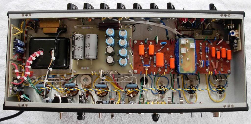
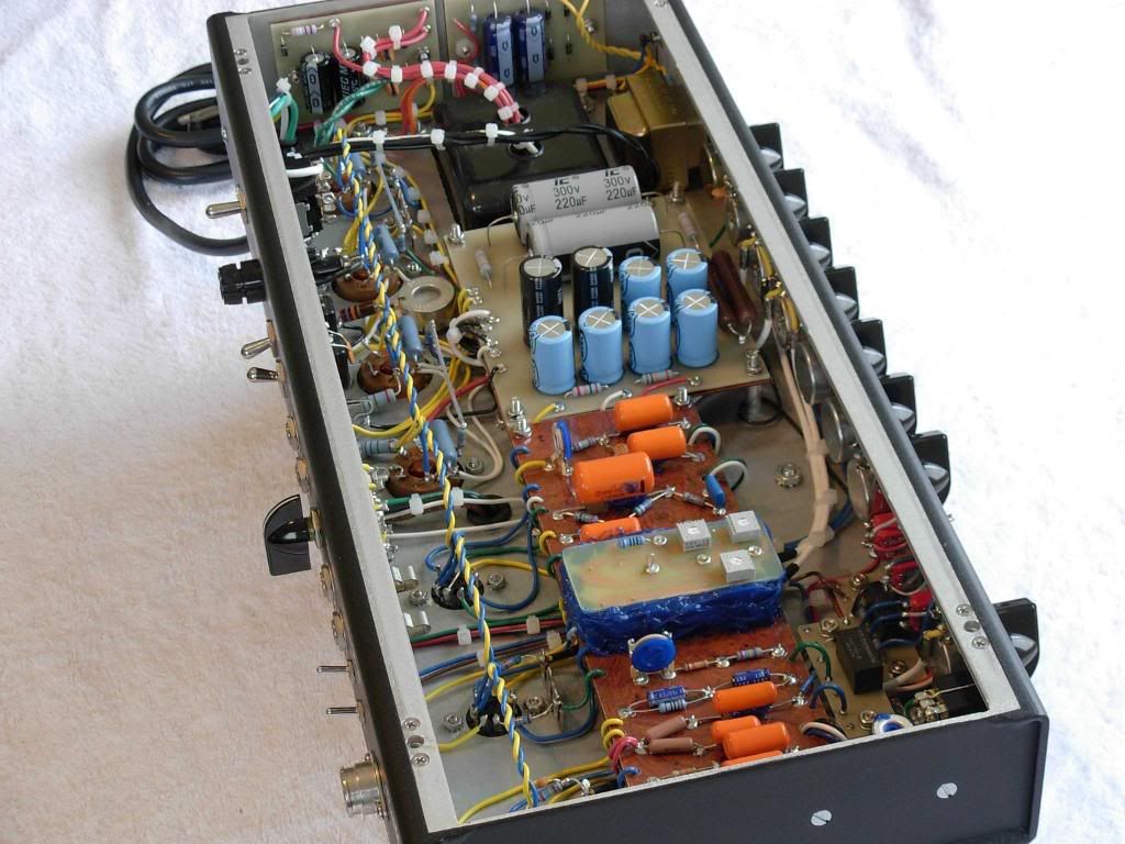
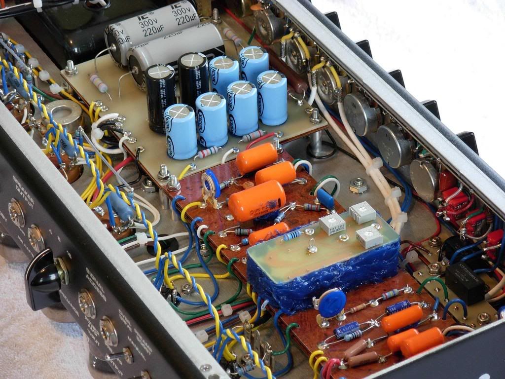
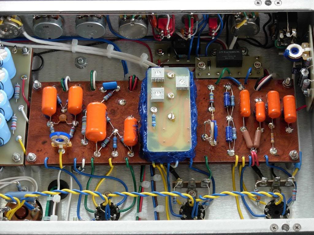
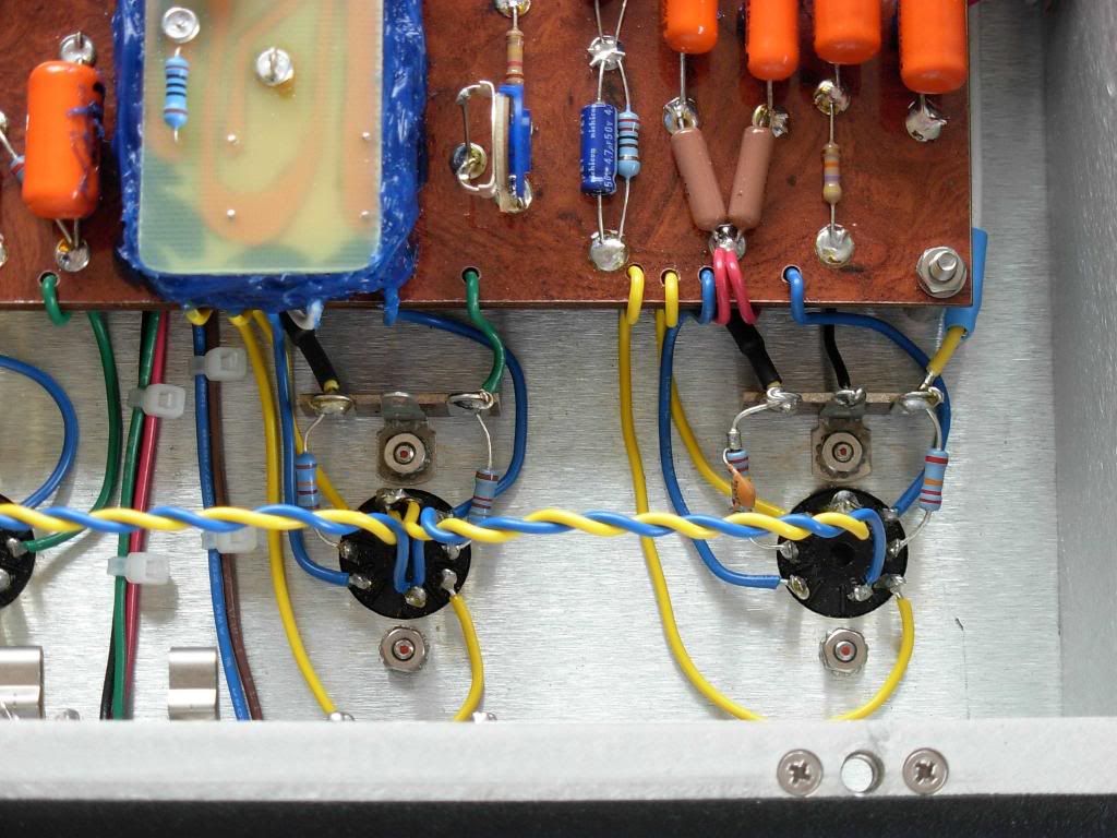
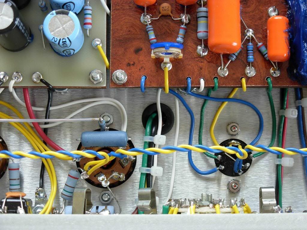
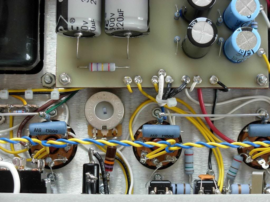
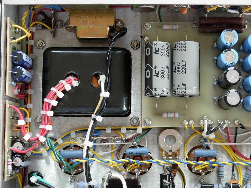
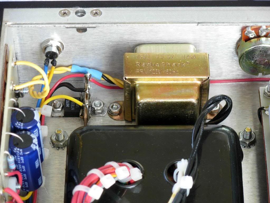
Below, you’ll find a bunch of pictures of the amp. Enjoy!
[IMG508]http://i205.photobucket.com/albums/bb17 ... on/BM1.jpg[/img]
[IMG
[IMG
[IMG
[IMG
[IMG
[IMG
[IMG
[IMG
[IMG
[IMG
[IMG
[IMG
[IMG
Re: 100W Bluesmaster is Born
Very, very nice!!
-
martin manning

- Posts: 14308
- Joined: Sun Jul 06, 2008 12:43 am
- Location: 39°06' N 84°30' W
Re: 100W Bluesmaster is Born
Fantastic, just Fantastic!UltraHookedOnPhonix wrote: Finally, after a year of working on this thing...
Is there a typo here?UltraHookedOnPhonix wrote:V3 Triode (PI)
Input-side Plate, Pin 6: 270V
Feeback-side Plate, Pin 1: 242V
Cheers,
MPM
Re: 100W Bluesmaster is Born
Clean Machine
-
UltraHookedOnPhonix

- Posts: 414
- Joined: Thu Dec 15, 2005 9:32 pm
- Location: Dumbleland
Re: 100W Bluesmaster is Born
Guys, thank you all so much!
[IMG592]http://i205.photobucket.com/albums/bb17 ... Layout.jpg[/img]
Because I didn’t like how the HRM board flopped around with three wires supporting it. It might look like I got a little over enthusiastic with the RTV but it’s actually just an outline built up around the edges of the HRM board. So it's actually hollow!Structo wrote:Nice and clean looking, except the goop. Why?
When the coax cable has been prepared, I push the signal lead into the pot lug hole and solder it, then you can manipulate the wire to make the shield rest on the pot case. To temporarily secure the rest of the wire, I put some scotch tape over the cable to keep it in suspended animation, then solder the shield. The case of the CTS pots are a pleasure to deal with because they accept solder really well.Structo wrote:I have a question for you guys that solder the shield like that to the pots.
How do you keep the cable tight to the pot while soldering that?
Stort Tack!!! (translation: Big Thanks)bluesfendermanblues wrote:Jättesnygg!!
I have not put a bright cap on the OD volume yet because I’m curious to hear how it works without it.Guitarman18 wrote: Have set it up for use with your D'lator?
Cheers,
Paul.
No, not yet. I just got it back. I’m currently wiring up a 2x12 to go with it.Tonegeek wrote:Easy on the eyes for sure. Got any clips?
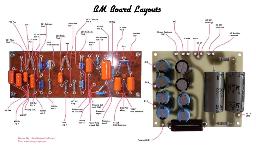
I really dig this circuit. Here’s a somewhat crude board layout I used for this build:M Fowler wrote:Very nice build how do like this amp? Its something I want to get started on but trying to sort out the board layouts.
[IMG
 592]http://i205.photobucket.com/albums/bb17 ... Layout.jpg[/img]
Thank you! Yes, it does have a cab. It’s from Brandon’s company.David Root wrote:Wonderful job! Very clean work and I bet it sounds as good as it looks. Does it have a cabinet yet?
Billy deserves a bottle after seeing him get zapped on the PI balance trimmer…OUCH!!!jelle wrote:Now that's a great project!
Big shout to Billy too, you both deserve a shot of Woodsford Reserve.
It’s possible I recorded the voltage incorrectly when taking notes. With a balanced tube and the PI trimmer set halfway, I’d expect them to be roughly 250V per side. I dunno…martin manning wrote:
“Input-side Plate, Pin 6: 270V
Feeback-side Plate, Pin 1: 242V”
Is there a typo here?
Cheers,
MPM
-
gilgalad101
- Posts: 51
- Joined: Sun Aug 31, 2008 6:06 pm
- Location: South Carolina
Re: 100W Bluesmaster is Born
Very impressive! I hope my build turns out at least half as pretty as yours. Thanks for posting those board layouts.

Re: 100W Bluesmaster is Born
Thanks for information and once again very impressive build.I really dig this circuit. Here’s a somewhat crude board layout I used for this build:
Mark
Re: 100W Bluesmaster is Born
Kind of a stupid basic question, but what are the blue capacitors on your power board? The ones I got from Mouser were smaller in diameter and green (47uf/250v).
Re: 100W Bluesmaster is Born
The blue caps are Xicon brand.
Re: 100W Bluesmaster is Born
The HRM board can be supported by taller nylon or plastic stands isn't that what one should do?
Re: 100W Bluesmaster is Born
That is what I would do.
Either mount the new screws to the board or make them go down to the chassis then standoffs to the main board and then standoffs to the HRM board with long screws.
Either mount the new screws to the board or make them go down to the chassis then standoffs to the main board and then standoffs to the HRM board with long screws.
Tom
Don't let that smoke out!
Don't let that smoke out!
Re: 100W Bluesmaster is Born
Thanks Tom thats what I was planning to do.
I have never built a Dumble amp and have two chassis to fill up. One will be the HRM BM the other maybe a two holer, not sure. So I'll be asking all kinds of questions, right now the boards are my main problem.
I have never built a Dumble amp and have two chassis to fill up. One will be the HRM BM the other maybe a two holer, not sure. So I'll be asking all kinds of questions, right now the boards are my main problem.
Re: 100W Bluesmaster is Born
Are you planning to make some PCB's for it?
Tom
Don't let that smoke out!
Don't let that smoke out!