My first Rocket... Need help!
Moderators: pompeiisneaks, Colossal

Re: My first Rocket... Need help!
It looks like there are a few turrets where the component is in the hole but is not soldered in - the V1a blocking cap on the control panel side for example. I would check to make sure every thing is soldered , and maybe look at every turret/component connection because some of them look kind of questionable.
You do not have the required permissions to view the files attached to this post.
-
amplifiednation
- Posts: 2091
- Joined: Sun Dec 26, 2010 6:19 pm
- Location: Boston
- Contact:
Re: My first Rocket... Need help!
If you pull your tubes you should be able to read voltage across the filter caps to see if they are wired properly. I cant remember getting much, if any, drop between caps with no tubes (keep your rectifier in)
I think you should reflow the joints that kt66 mentions as well. Even if one of those connections is poor then power wont properly flow through the circuit.
On the cathode of the first triode of v1 the 1k5 resistor and 22uf cap should be wired in parallel to ground. Are they? I know you had mentioned adding a boost and removing it, I'm just curious if you removed the wrong cap. It appears (to me) like the "boost cap" is still there attached to a jumper. I cant make out the wiring there.
Last edited by amplifiednation on Thu Mar 10, 2011 1:10 pm, edited 3 times in total.
Amplified Nation
www.amplifiednation.com
@ampnation
www.amplifiednation.com
@ampnation

Re: My first Rocket... Need help!
Ian,
here are couple of build tips for you to consider in your own time. These two links helped my soldering technique become 100% reliable and made the single biggest improvement to how my builds sounded:
http://workmanship.nasa.gov/lib/insp/2% ... ments.html
This second link actually refers to soldering ceramic strips but at about 3/4 of the way through it explains getting just the right amount of solder on the tip to get efficient transfer of heat. A nice video when you have 12 minutes to spare.
http://www.classictek.org/index.php?opt ... &Itemid=80
Re: My first Rocket... Need help!
KT66 wrote:It looks like there are a few turrets where the component is in the hole but is not soldered in - the V1a blocking cap on the control panel side for example. I would check to make sure every thing is soldered , and maybe look at every turret/component connection because some of them look kind of questionable.
I will definately go back and soder those.
Also, I did remove the cathode bypass cap off of the second? triode in an attempt to reduce gain, pin 8 of v1. (I read that off of another post here on TAG) The other cap is attached via spdt switch off of the first triode's cathode in v1, pin 3. Should I just put it back on?
My B+ 4, 5 leads are wired underneath the board and stuck up into the turrent from underneath. I will go trace those to double check.
Ange pointed me to Ron's rocket build and after reviewing it I nocticed besides my lead dress needing work, I grounded my filter caps differently than his. Should I ground them as he has done in his build or does it make a difference? Mine are all going to the same ground off on the cap closest to the preamp board.
What will I be looking for when I check the voltages across the filter caps? Do I just probe each positve lead and take down the voltage?
Thanks everyone!
Ian
-
amplifiednation
- Posts: 2091
- Joined: Sun Dec 26, 2010 6:19 pm
- Location: Boston
- Contact:
Re: My first Rocket... Need help!
My thoughts were that if the cathode bypass cap isn't there on V1 maybe it's pulling too much juice, throwing your B5 up a little bit. I would un-jumper the boost for now, its so easy to rewire that jumper and wire back in C1 as that the way it's . If it's a noticecable difference when shut off, and you know the switch is working then just switch it off I guess.showsii wrote:KT66 wrote:It looks like there are a few turrets where the component is in the hole but is not soldered in - the V1a blocking cap on the control panel side for example. I would check to make sure every thing is soldered , and maybe look at every turret/component connection because some of them look kind of questionable.
I will definately go back and soder those.
Also, I did remove the cathode bypass cap off of the second? triode in an attempt to reduce gain, pin 8 of v1. (I read that off of another post here on TAG) The other cap is attached via spdt switch off of the first triode's cathode in v1, pin 3. Should I just put it back on?
My B+ 4, 5 leads are wired underneath the board and stuck up into the turrent from underneath. I will go trace those to double check.
Ange pointed me to Ron's rocket build and after reviewing it I nocticed besides my lead dress needing work, I grounded my filter caps differently than his. Should I ground them as he has done in his build or does it make a difference? Mine are all going to the same ground off on the cap closest to the preamp board.
What will I be looking for when I check the voltages across the filter caps? Do I just probe each positve lead and take down the voltage?
Thanks everyone!
Ian
I'm a newbie on here, but I JUST built and troubleshot my rocket.
you can measure right off the caps. with the tubes in and B+ moving the way it was supposed to, you should see a few volt drop from each node, and those same readings should be at the connected turrets.
don't forget to drain your caps...(disclaimer!!!!)
Amplified Nation
www.amplifiednation.com
@ampnation
www.amplifiednation.com
@ampnation
Re: My first Rocket... Need help!
amplifiednation wrote:My thoughts were that if the cathode bypass cap isn't there on V1 maybe it's pulling too much juice, throwing your B5 up a little bit. I would un-jumper the boost for now, its so easy to rewire that jumper and wire back in C1 as that the way it's . If it's a noticecable difference when shut off, and you know the switch is working then just switch it off I guess.showsii wrote:KT66 wrote:It looks like there are a few turrets where the component is in the hole but is not soldered in - the V1a blocking cap on the control panel side for example. I would check to make sure every thing is soldered , and maybe look at every turret/component connection because some of them look kind of questionable.
I will definately go back and soder those.
Also, I did remove the cathode bypass cap off of the second? triode in an attempt to reduce gain, pin 8 of v1. (I read that off of another post here on TAG) The other cap is attached via spdt switch off of the first triode's cathode in v1, pin 3. Should I just put it back on?
My B+ 4, 5 leads are wired underneath the board and stuck up into the turrent from underneath. I will go trace those to double check.
Ange pointed me to Ron's rocket build and after reviewing it I nocticed besides my lead dress needing work, I grounded my filter caps differently than his. Should I ground them as he has done in his build or does it make a difference? Mine are all going to the same ground off on the cap closest to the preamp board.
What will I be looking for when I check the voltages across the filter caps? Do I just probe each positve lead and take down the voltage?
Thanks everyone!
Ian
I'm a newbie on here, but I JUST built and troubleshot my rocket.
you can measure right off the caps. with the tubes in and B+ moving the way it was supposed to, you should see a few volt drop from each node, and those same readings should be at the connected turrets.
don't forget to drain your caps...(disclaimer!!!!)
Yeah the switch Is working, there is a pretty big difference, but I still am not opposed to removing it!
Ok, So B+ 2,3,4,5 are Caps 15,16,17,18 respectively? That drop across each cap should line up closely to the B+ voltages on the rocket voltage chart?
Drain the caps, got it. Always a good reminder.
Ian
-
amplifiednation
- Posts: 2091
- Joined: Sun Dec 26, 2010 6:19 pm
- Location: Boston
- Contact:
Re: My first Rocket... Need help!
I listened to your clip, and the amp sounds good....so you're almost there...there is got to be something very small thats causing the increased gain. So if you've got a boost installed...my thought was just to disconnect it for now so you can eliminate that as an issue.
the cap on the cathode of V1 is part of the original rocket build and I'm not sure of the ramifications of removing it as to how it would effect your voltages overall. Keeping it in might reduce your B5 (one of the gurus will have to chime in)
In my build my voltages were TOTALLY off, and it ended up being just ONE resistor that I was off and then everything came together and the B+ went were it was supposed to. If you have more voltage on B5 than B4, you have a problem and it's probably in the board somewhere.
Check continuity as suggested by the other members to make sure you have the underboard jumpers going to the right spot...if you made a mistake you can change the wiring from the cap stack to the board to fix it.
I would double check your resistors using one of the "color band cacluators" online, because you can't check with them in the circuit.
I have a feeling that its going to be a very small mistake. If you're lucky one of the big dogs will jump in and probably identify it quickly
Amplified Nation
www.amplifiednation.com
@ampnation
www.amplifiednation.com
@ampnation

pots
Look at your pots and the ground solder connections. They are beaded and not pooled flat to the pot. Be sure that your ground continuity readings are looking good. Its a good idea to lightly scuff the backs of the pots with sandpaper to make a good surface for the solder bond.
A
PS be sure and report back on the various points, jumpers under board, caps and resistors back to spec, and reflow solder joints.
A
PS be sure and report back on the various points, jumpers under board, caps and resistors back to spec, and reflow solder joints.
Update
Hello Everyone,
Here is a list of tasks I have completed, have not completed and have questions about.
Completed:
Checked plate resistors
Checked volume pot taper
Check for and re flowed soder joints
Check pot grounds and all other grounds. All measure 0v
Rewired input sector, cleaned up shielded leads with heat shrink.
Re dressed leads on V1 V2 V3.
Redressed/re wired b+ leads from caps to board.
Disconnected boost previously installed
Re wired original 22uf cathode bypass cab off V1b
NOT Completed:
Trying different tubes
Checking OT
Playing through different ohm setting
Measure Voltage across filter caps
Questions:
Should I measure b+ voltage across caps while amp in ON with tubes IN?
What is the purpose of using the color band resistor calculator compared to using multimeter inside the amp to check resistors?
It seems that my increase in B+5 voltage might be the problem, what are the steps to troubling shooting that?
Any more suggestions to get this thing running right??
Thanks
Ian
-
amplifiednation
- Posts: 2091
- Joined: Sun Dec 26, 2010 6:19 pm
- Location: Boston
- Contact:
Re: Update
you can't measure a resistor once it's connected to a circuit. if you use a color band calculator you can decipher what values the resistors are without pulling them out.showsii wrote:
Questions:
Should I measure b+ voltage across caps while amp in ON with tubes IN?
What is the purpose of using the color band resistor calculator compared to using multimeter inside the amp to check resistors?
It seems that my increase in B+5 voltage might be the problem, what are the steps to troubling shooting that?
Measure B+ with tubes out and record those readings, then with tubes in.
B5 connects to R4, B4 connects to R6, B3 connects to R16 and R15. What layout are you using? The rocket layout in the files section is pretty clear. I attached it.
You do not have the required permissions to view the files attached to this post.
Amplified Nation
www.amplifiednation.com
@ampnation
www.amplifiednation.com
@ampnation
B+3 B+4
You can see the connections. Although this layout is a bit different than the classic rocket ( It has reverb and boost ), all other connections are consistent.
B+4 - R6
B+3 - R15 R16 juncture
[IMG 1084]http://i260.photobucket.com/albums/ii9/angelodp1/72.jpg[/img]
B+4 - R6
B+3 - R15 R16 juncture
[IMG
 1084]http://i260.photobucket.com/albums/ii9/angelodp1/72.jpg[/img]
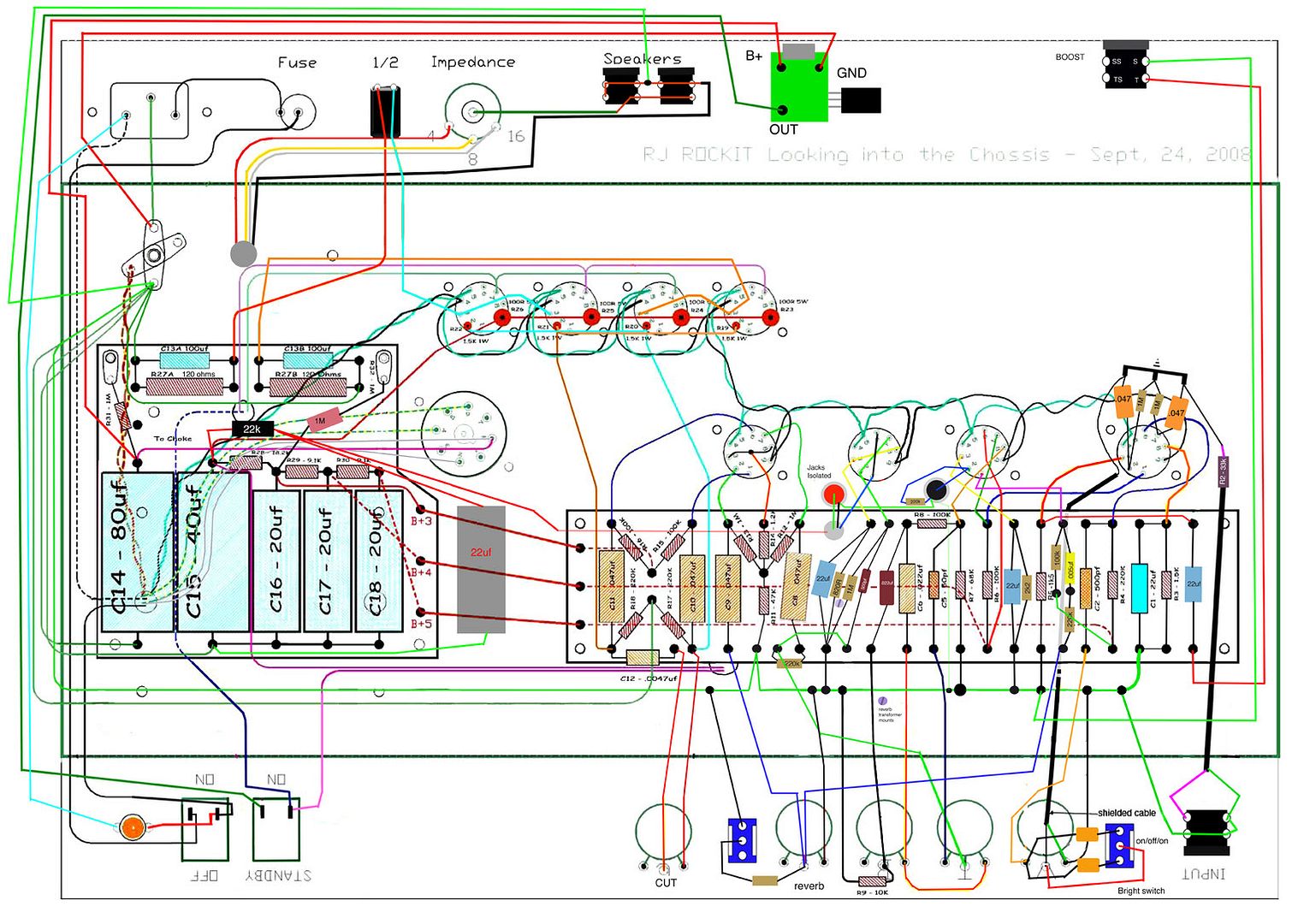
New pictures
Ok everyone, As requested by Ange I have tried to take some better photographs so that one of y'all might catch what is wrong with this amp.
UPDATE: I have a few new voltage readings. I removed the bleed resistors to see if that would help anything. Voltages-yes The lack of headroom- NO. So we still have some problems.
V1-
a
plate-111.4
Cathode- .89
b
Plate- 86.6
cathode- .64
V2
Plate- 186.4
Grid- 111.3
Cathode- 112.1
PI
a
Plate- 168
Grid- 28.9
Cathode43.1
b
Plate164.8
Grid- 28.34
Cathode- 43.1
B+1- 282.6
B+2- 279
B+3- 210.4
B+4- 185.4
B+5- 181.7
Have not taken readings off v4,5,6,7 yet.
You do not have the required permissions to view the files attached to this post.
Re: My first Rocket... Need help!
Ian, I have taken a long old squint at the new photos. I admit to getting rather confused tracing this & really lost the plot in the PI section.
On the rectifier socket, could you dress your green/yellow wire that runs to the first filter cap so that it does not rub the AC pin? I know that space is tight there and it will not fix the problem at hand, but it may prevent another one later.
Are those burn marks on the insulation of the 5V wires leading to the rectifier? (Grey wires in the middle of the image below)
Apart from that, out of curiosity did you use any secondhand wire on the amp?
You do not have the required permissions to view the files attached to this post.