martin manning wrote:I'm still looking at V2a's plate being 55V when it's supposed to be connected directly to B+4, which is 83V.
I wonder if V2b is being used as the cathode follower. Its plate is at 82V in this case. I can't see the pictures while I'm here at work but you may want to check to see if that is the case. I don't see what would cause it to be 55V unless he has a resistor soldered to the wrong place.
Yes, that looks like the case, and V2a and b appear to be wired correctly, but, the cathode resistor on V2b doesn't look like 56k.
I can't tell too well at the moment. I'll take a look at that when I get home. So that's another thing for him to look at.
EDIT: Your right. I can't tell what the value is but it doesn't look like a 56k or a 100k like I have seen. This should be checked first.
M Fowler wrote:It's suppose to be a 68k resistor there based on the layout he is using.
I think I'm on with the 68k. I gotta get some better data and get back to you geniuses. I am up in the mountains of new hampshire and need to get back to the build
It's R7 on the schematic, shown as 56k there. Hard to tell for sure, but the pic looks like a 120R on the board. A small value would explain the high current draw from B+4 and the low voltages we're seeing.
Taylor, this can wait! You need to enjoy what ever it is you're doing up there and whomever you're doing it with. BTW, I climbed Mt. Washington one beautiful sunny late-December day... what a great place!
martin manning wrote:It's R7 on the schematic, shown as 56k there. Hard to tell for sure, but the pic looks like a 120R on the board. A small value would explain the high current draw from B+4 and the low voltages we're seeing.
Taylor, this can wait! You need to enjoy what ever it is you're doing up there and whomever you're doing it with. BTW, I climbed Mt. Washington one beautiful sunny late-December day... what a great place!
Trust me all I want to be doing is getting the amp running! There was like a foot of snow here too. Will just a few hours and hopfully this is sorted out!
I have not done readings since I added the reverb circuit. Here are my voltages. My topology varies slightly from Normster's so it will reflect on the tables.
M Fowler wrote:It's suppose to be a 68k resistor there based on the layout he is using.
So finally made it home. I don't know if that resistor is correct. Honestly I can't read the colors because it's so small.
When I bought the parts I was supposed to have 10 68k resistors and I can't find the bag (I have all the others) so I'm not sure if I used the wrong one, because why would it look so different than the others??
You do not have the required permissions to view the files attached to this post.
That does look like a 100ohm resistor, which would explain the huge drop in voltages. You could really use anything between 56k and 100k if you had those for now.
Check it with your multimeter and see what it says. If it is in fact 100, or really anything below 56k you should replace it with a larger value.


 2603]
2603]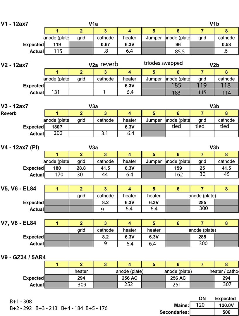