
V1 voltages are that low on a Rocket.Fischerman wrote:Another thought: Anybody know what preamp voltages to expect? Running it with the second stage on V1 (like a 'Wreck) or V2 (like a Vox) will definitely affect the voltages and, just as a wild guess here, it looks like our first stage plate voltage is going to be very low, especially if wired like a 'Wreck. Should we be surprised if our first stage plate voltage is, say 90vdc?
EDIT: Did some 'Wrecks use a single 9.1k first dropping resistor instead of 18k? Is that sometimes the case on these lower voltage amps?
Building a Rocket - Layout Check for group build
Moderators: pompeiisneaks, Colossal
Re: Building a Rocket - Layout Check for group build
Completely corrected, updated layout
deleted. Look at reposted schematics and layout, dated june 9, 2008..
Last edited by Sven on Mon Jun 09, 2008 8:03 am, edited 1 time in total.
Re: Building a Rocket - Layout Check for group build
deleted
Last edited by Sven on Sun Jun 22, 2008 2:32 pm, edited 2 times in total.
-
Ron Worley

- Posts: 908
- Joined: Mon Dec 24, 2007 8:21 pm
- Location: Keller, TX
Re: Building a Rocket - Layout Check for group build
Sven-
What I am hearing suggests that this layout is still not right- there is NO PS board, and the 80uf cap is really 2 40's strung together... giving you a Stack o' Caps that looks exactly like it does in an Express or Liverpool...
The dropping resistors are attached directly to the 40uf caps...
Ron
What I am hearing suggests that this layout is still not right- there is NO PS board, and the 80uf cap is really 2 40's strung together... giving you a Stack o' Caps that looks exactly like it does in an Express or Liverpool...
The dropping resistors are attached directly to the 40uf caps...
Ron
-
Fischerman
- Posts: 819
- Joined: Thu Dec 07, 2006 3:47 pm
- Location: Georgia
Re: Building a Rocket - Layout Check for group build
I thought all that was understood? I dunno about others in the group but I'm just building an amp...I've always hated that big pile of caps glued together anyway...we can do better than that. These are our own custom amps...we don't have top settle for piles of glued caps and Dymo labels. If you're making a clone that's different but I'm not making a clone.What I am hearing suggests that this layout is still not right- there is NO PS board, and the 80uf cap is really 2 40's strung together... giving you a Stack o' Caps that looks exactly like it does in an Express or Liverpool...
The dropping resistors are attached directly to the 40uf caps...
I'm not sure if two 40s in parallel sounds any different than one 80...either way it's 80uF and I would be surprised if the ESR made an audible difference. Doesn't matter...I'm not using either value...I'm using two 33uFs in parallel...and probably only 20uF for the screens.
-
gregarious
- Posts: 49
- Joined: Mon May 08, 2006 11:21 am
The "tone" of filter caps
Fischerman
I've read bigger caps deliver more thump for bass notes therefore the implementation of parallel caps. I'm with you on the aesthetics of the power section layout - if you have the real estate and placement is made so as not to introduce interference into the circuit, is the stacking technique required?
Are there downsides to over-filtering? There seems to be more filtering in modern circuits compared to the designs of the 50's & 60's - cost of the cap or ...?
Point of understanding, provided the filter cap is in value range of the rectifier used, what tonal impact does that value play in the circuit?
I'm not sure if two 40s in parallel sounds any different than one 80...either way it's 80uF and I would be surprised if the ESR made an audible difference. Doesn't matter...I'm not using either value...I'm using two 33uFs in parallel...and probably only 20uF for the screens.Some AC30s only had 16uF for the first node and then 16uF for the screens.
I've read bigger caps deliver more thump for bass notes therefore the implementation of parallel caps. I'm with you on the aesthetics of the power section layout - if you have the real estate and placement is made so as not to introduce interference into the circuit, is the stacking technique required?
Are there downsides to over-filtering? There seems to be more filtering in modern circuits compared to the designs of the 50's & 60's - cost of the cap or ...?

Re: The "tone" of filter caps
Actually the mfg spec for a 5ar4 is 60mf max. Ken always put his first filter cap before the standby switch. (At least in all of the pics I have seen) This allows the 1st cap to charge up gradually as the recto tube (in this case) comes up to temperature and voltage. If he had put the 1st filter cap after the standby switch then you would be really taxing the current demand on the recto tube when you fliped the standby switch to operate.gregarious wrote:FischermanPoint of understanding, provided the filter cap is in value range of the rectifier used, what tonal impact does that value play in the circuit?
I'm not sure if two 40s in parallel sounds any different than one 80...either way it's 80uF and I would be surprised if the ESR made an audible difference. Doesn't matter...I'm not using either value...I'm using two 33uFs in parallel...and probably only 20uF for the screens.
I've read bigger caps deliver more thump for bass notes therefore the implementation of parallel caps. I'm with you on the aesthetics of the power section layout - if you have the real estate and placement is made so as not to introduce interference into the circuit, is the stacking technique required?
Are there downsides to over-filtering? There seems to be more filtering in modern circuits compared to the designs of the 50's & 60's - cost of the cap or ...?
It is possible that two 40uf caps can have a larger surface area for its plates than 1 80uf cap. ESR can also come into play when paralleling caps
Most of the power from an amp is used to produce bass notes. A properly built power supply has to be able to deliver the current demand to produce those notes. Larger caps can store more energy and give it up very quickly. You will reach a point where adding more capacitance becomes useless as they won't be needed. Too much capacitance can also cause motorboating and ghost notes.
Most amps today use solid state diodes instead of rectifier tubes. They are cheaper and rarely have to be replaced like a Rectifier tube . The rectifier tube does add some sag and compression to the power supply (depending on the design) and some players prefer this "feel" to their amp's response. SS diodes don't have the problem of max capacitance as long as they are rated enough to handle the charging current.
I have built a few TW "inspired" amps without the stack of caps and I can say that I have found no difference in tone using the same value caps but in a different layout. I have switched the Express I am working on at the moment to can style caps and will try and give a tone report and maybe some sound files as soon as I get it completed so you can judge for yourself.
Just my 2 cents. YMMV
-
Fischerman
- Posts: 819
- Joined: Thu Dec 07, 2006 3:47 pm
- Location: Georgia
Re: Building a Rocket - Layout Check for group build
greg,
Less PS capacitance can make the amp feel more 'squishy, for lack of a better word and more capacitance can make it stiffer. Some people might say that an AC30 is supposed to get kinda flabby when cranked...others might disagree. I've never owned one so I dunno. IIRC, there were early 100W Plexi amps (some of the 'grail-est' of Plexis IIRC) that had two 32uFs in series for the screens...16uF net on a 100W amp. The first node (OT center tap) is where all the power 'current' is...not nearly as much at the screens but the screen voltage has a big affect on the plate current (edit: and the choke provides resistance to changes in current so there is sort of a 'barrier' between those two nodes).
I went with two 33uFs for the first node because I have it on hand and I think it's sufficient. I agree with Dana; IMLE, 80uF for the first node is no problem at all for the GZ34 the way it's done here. A non-issue IMO.
After more thought, I've got the caps and the room and I haven't cut/drilled my boards yet so I might add a second 20uF in parallel for the screens (for 40uF total).
And caps of the 50s/60s were much more expensive and physically large than today so there were restrictions.
Since we're using a rectifier with an indirectly heated cathode (i.e. it warms up slowly)...that means they can put the cathode closer to the plate which results in less voltage drop. There's probably other rectifiers we can use (5U4 I think) to get more sag...probably none (other than a SS plug-in) to get less. The KCA site has this nice little Rectifier Compatibility page. Don't know if 3A filament current is a problem for these PTs.
Re: Building a Rocket - Layout Check for group build
UR12 wrote:Most amps today use solid state diodes instead of rectifier tubes. They are cheaper and rarely have to be replaced like a Rectifier tube . The rectifier tube does add some sag and compression to the power supply (depending on the design) and some players prefer this "feel" to their amp's response.
In this application, the GZ34 is not going to produce much sag -I think that is what Fischerman is saying - because its design voltage drop is for a much larger current demand that will be presented in the Rocket.Fischerman wrote:There's probably other rectifiers we can use (5U4 I think) to get more sag...probably none (other than a SS plug-in) to get less.
If one wants to dial in more sag in this build, it will probably be best achieved by tweaking the value of a dropping resistor substituted for the choke. I had a communication from an old Vox engineer many years ago that was touting exactly that - a 300 to 500 ohm resistor (much as you see the "Robben Ford" mod in a Dumble-derived amp).
If one is open to building a Rocket without making an exact clone of an amp that we don't have to copy, I'd suggest going with a solid state rectifier (vs GZ34) and a 300 ohm resistor (vs choke).
-
RJ Guitars

- Posts: 2663
- Joined: Tue Nov 14, 2006 3:49 am
- Location: Los Alamos, New Mexico
- Contact:
Choke - Proper orientation is?
Hello Guys,
I hate to interrupt good technical discussion like we are getting in sorting out the finer parts of building a Trainwreck amp... but I have a question about how to orient the choke.
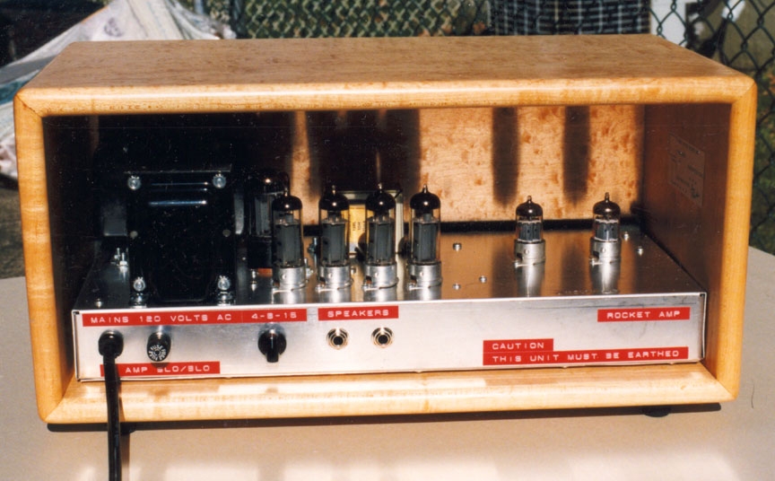
It makes sense to me that you would want the laminations on the choke running the same direction as the laminations on the power transformer... now that is just my inclination but I won't claim to know that absolutely. Can anyone tell me what is correct? I've seen pictures of quality amps with them going either direction... On the limited info available on a Rocket I cannot see all three transformers well enough to figure it out
And also, here is a look at chassis #1 for our Rocket group build. They turned out really nice and I plan to start shipping them out this weekend.
If anyone wants to joins us, I have a few extra packages. For this first run everything is sold at cost and as you can see, the components are first rate.
Check out Eric's (Lone Raven) work on these front panels. He has four different designs available and they all look great!
rj
I hate to interrupt good technical discussion like we are getting in sorting out the finer parts of building a Trainwreck amp... but I have a question about how to orient the choke.
It makes sense to me that you would want the laminations on the choke running the same direction as the laminations on the power transformer... now that is just my inclination but I won't claim to know that absolutely. Can anyone tell me what is correct? I've seen pictures of quality amps with them going either direction... On the limited info available on a Rocket I cannot see all three transformers well enough to figure it out
And also, here is a look at chassis #1 for our Rocket group build. They turned out really nice and I plan to start shipping them out this weekend.
If anyone wants to joins us, I have a few extra packages. For this first run everything is sold at cost and as you can see, the components are first rate.
Check out Eric's (Lone Raven) work on these front panels. He has four different designs available and they all look great!
rj
You do not have the required permissions to view the files attached to this post.
Last edited by RJ Guitars on Thu May 08, 2008 2:18 pm, edited 1 time in total.
Good, Fast, or Cheap -- Pick two...
http://www.rjguitars.net
http://www.rjaudioresearch.com/
http://diyguitaramps.prophpbb.com/
http://www.rjguitars.net
http://www.rjaudioresearch.com/
http://diyguitaramps.prophpbb.com/
-
Fischerman
- Posts: 819
- Joined: Thu Dec 07, 2006 3:47 pm
- Location: Georgia
Re: Building a Rocket - Layout Check for group build
It's visible in this photo in the Files section. Opposite what you have in your pic...it's oriented the same as the OT.
-
RJ Guitars
- Posts: 2663
- Joined: Tue Nov 14, 2006 3:49 am
- Location: Los Alamos, New Mexico
- Contact:
Re: Building a Rocket - Layout Check for group build
it's pretty clear about the choke there.... but is that power tranny a laydown with the laminations running horizontal or is it oriented like the choke with the laminations vertical?Fischerman wrote:It's visible in this photo in the Files section. Opposite what you have in your pic...it's oriented the same as the OT.
Now the power tranny is working with all AC while the choke is working with rectified DC... that might make my previous inclination wrong since we want to keep the AC from coupling back into the choke.
So a couple fundamental questions:
1) Could there be any potential coupling hum from the power tranny into the choke...
or
2) Could there be any coupling hum from the choke into the output tranny.
rj
Good, Fast, or Cheap -- Pick two...
http://www.rjguitars.net
http://www.rjaudioresearch.com/
http://diyguitaramps.prophpbb.com/
http://www.rjguitars.net
http://www.rjaudioresearch.com/
http://diyguitaramps.prophpbb.com/
-
Fischerman
- Posts: 819
- Joined: Thu Dec 07, 2006 3:47 pm
- Location: Georgia
Re: Building a Rocket - Layout Check for group build
To me it looks like you can see the endbells sticking out from behind the OT so it looks stand-up to me. And of what I can see sticking out from behind the OT...it looks smooth like an endbell and not like stacked laminations.
Also look at the mounting bolt at the left. It looks different than the OT mounting (i.e. the bolt head is outside the chassis for the OT but looks like it's inside the chassis for the PT. But if it were laydown wouldn't you expect the 'bottom' lamination to be flush with the chassis with the mounting bolts going through the laminations with the nut (or bolt head) on top? And we should be able to see that nut (or bolt head) on top shouldn't we?
Also look at the mounting bolt at the left. It looks different than the OT mounting (i.e. the bolt head is outside the chassis for the OT but looks like it's inside the chassis for the PT. But if it were laydown wouldn't you expect the 'bottom' lamination to be flush with the chassis with the mounting bolts going through the laminations with the nut (or bolt head) on top? And we should be able to see that nut (or bolt head) on top shouldn't we?
-
txbluesboy
- Posts: 387
- Joined: Mon Apr 02, 2007 3:52 pm
- Location: Dallas area
- Contact:
Re: Building a Rocket - Layout Check for group build
I dont think that the orientation of the choke to the power transformer could make much difference. The relationship between the power transformer and the output transformer is much more critical in my opinion.
-
RJ Guitars
- Posts: 2663
- Joined: Tue Nov 14, 2006 3:49 am
- Location: Los Alamos, New Mexico
- Contact:
Extra Chassis
I had two PM's asking about extra chassis' today - but I see my responses are stuck in my outbox. All of my AmpGarage PM boxes are overflowing so I may have this system fully constipated right now... I'll give you an alternative contact email address...
rj@rjguitars.net
I indeed have the parts to cover those two requests so if you want to send me an email, I will send you the details.
The project is going great and for tomorrow I have plans of nothing but preparing responses to questions and queries about cost and shipping info. I'll follow that up with packing, labeling, weighing and shipping. I expect packages to start rolling out Monday and the balance to follow in short order.
rj
Last edited by RJ Guitars on Tue May 27, 2008 12:29 am, edited 1 time in total.
Good, Fast, or Cheap -- Pick two...
http://www.rjguitars.net
http://www.rjaudioresearch.com/
http://diyguitaramps.prophpbb.com/
http://www.rjguitars.net
http://www.rjaudioresearch.com/
http://diyguitaramps.prophpbb.com/