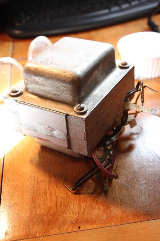
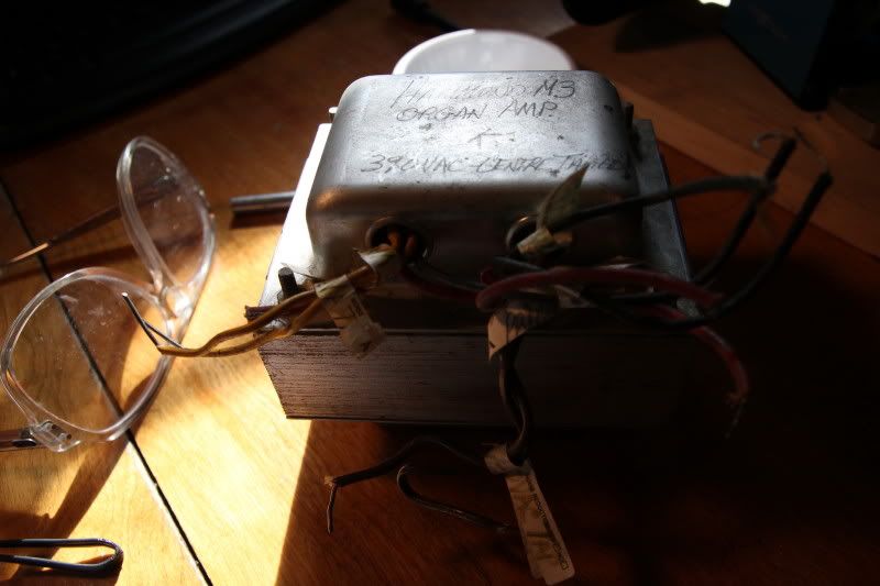
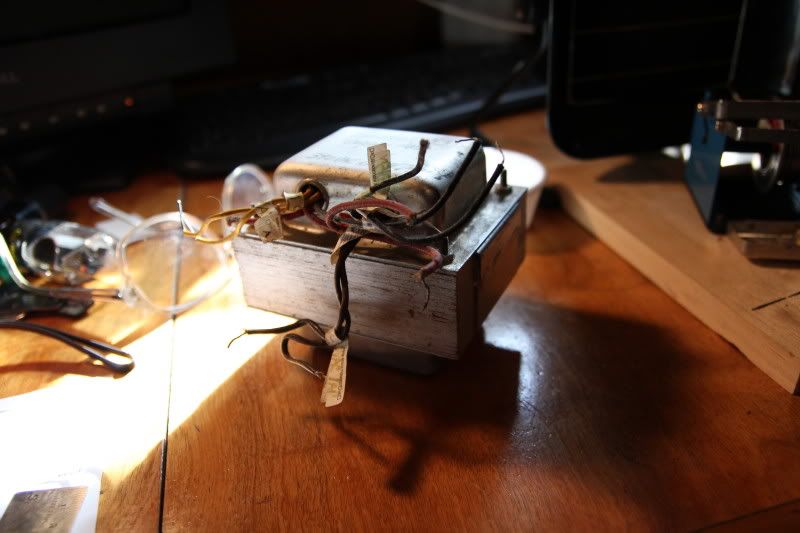
Here is my latest amp project. It started as a gnarly old Hammond M3 Organ power transformer I found on Kijiji (Canadian Craigslist):
[IMG:533:800]http://i291.photobucket.com/albums/ll31 ... 0003_2.jpg[/img]
[IMG:800:533]http://i291.photobucket.com/albums/ll31 ... 0002_2.jpg[/img]
[IMG:800:533]http://i291.photobucket.com/albums/ll31 ... 0001_2.jpg[/img]
This transformer is for a 6V6 push pull amp (2 power tubes) with around ten tubes total I think. While it's a beast of a piece of iron I read someone tried to run EL34s on it and it was smoking hot (no, not good).
I decided to build a 6V6 Trainwreck Express style amp. The PT runs nice and cool.
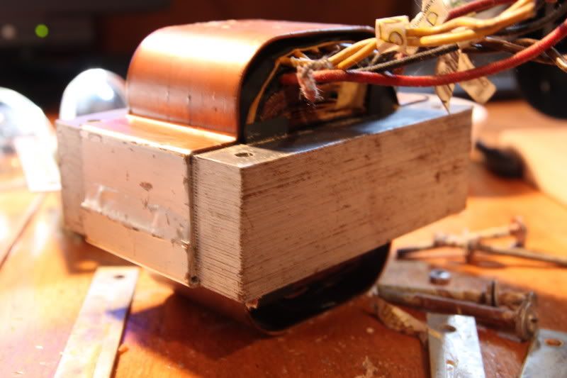
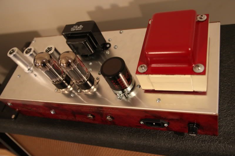
I opened the PT up and removed the 5V taps, heatshrinked everything, primed and painted the end bells, light top coat on the laminations and replaced the bolts and rubber coated washers:
[IMG:800:533]http://i291.photobucket.com/albums/ll31 ... 0001_3.jpg[/img]
Looks pretty slick now:
[IMG:800:533]http://i291.photobucket.com/albums/ll31 ... r_0005.jpg[/img]
Express build, new layout: The 6V6 Brainwrecker!
Moderators: pompeiisneaks, Colossal
-
ForcedFire

- Posts: 34
- Joined: Sat Mar 05, 2011 4:35 pm
-
ForcedFire
- Posts: 34
- Joined: Sat Mar 05, 2011 4:35 pm
Re: Express build, new layout: The 6V6 Brainwrecker!
This PT puts out a whopping 512V after the solid state rectifier. I have used 2 400V 150uF filter capacitors in series with 470k resistors across each cap for an 800V rating. This is on a card with the rectifier. I still have to goop the filter capacitors to make sure they do not vibrate.
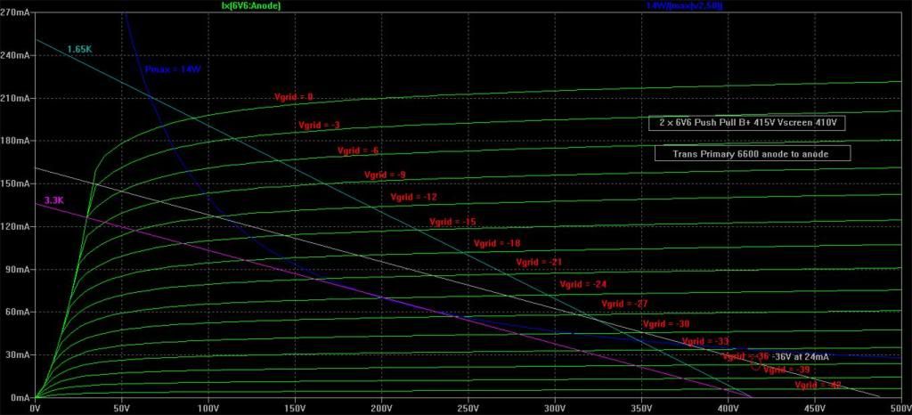
I used an ST Microelectronics STP9NK90Z MOSFET for the VVR. I have a resistor and trimpot to set the maximum value of the B+. The EL34 Trainwreck B+ I have seen online is around 395V. I chose 415V for my B+ with 6V6. I am using the JJ 6V6S matched set from thetubestore. I hate how they put that hideous sticker on the tubes but they are well matched (and I picked the sticker off...).
Here is the loadline for my amp:
[IMG 466]http://i291.photobucket.com/albums/ll31 ... d_Line.jpg[/img]
I have my tubes biased at 24-25mA. There is a slight mismatch in my OT (132ohms and 138ohms @ DC). I decided to use the Triode Electronics 6K6 primary Deluxe Reverb OT by Magnetic Components ($29!!!). This amp seems pretty close to a Deluxe Reverb PA with a hot rodded preamp.
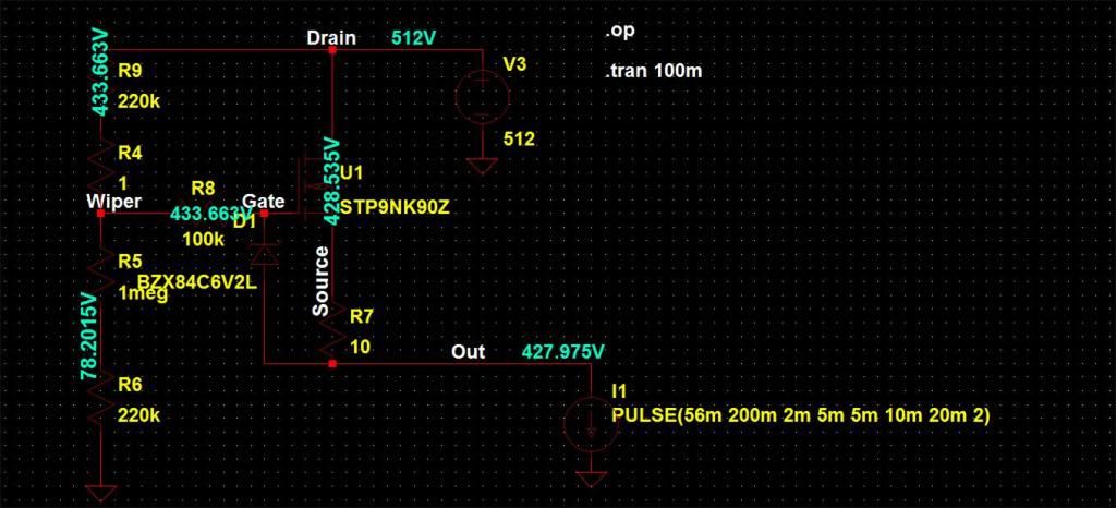
My MOSFET has an internal 30V zener. I wanted a lower value to limit the current so the MOSFET acts like a HT fuse. I tried 6.2V and it worked fine in practice but I simulated with the SPICE model of the MOSFET and it was shutting down with minimal current draw so I clipped out the 6.2V zener for now.
Here is the VVR in SPICE:
[IMG466]http://i291.photobucket.com/albums/ll31 ... AS/vvr.jpg[/img]
At no signal my amp draws 56mA from the supply. When simulating the whole amp, under full signal the power supply current draw goes up to 200mA! This seems a little high, but anyways I used a pulsed current source to model the draw from the VVR at no signal and with signal and using a 6.2V the MOSFET shuts down. The data sheet specs Rds(on) at 1.3ohms but that's at 3A, from the SPICE model it looks like the on resistance is a bit higher under the VVR conditions. In SPICE, a 12V zener is the ticket for this MOSFET in a VVR.
Here is the output voltage of the VVR, modeling the shut-down characteristic due to the low zener/high Rd(on):
[IMG466]http://i291.photobucket.com/albums/ll31 ... ed_off.jpg[/img]
I used an ST Microelectronics STP9NK90Z MOSFET for the VVR. I have a resistor and trimpot to set the maximum value of the B+. The EL34 Trainwreck B+ I have seen online is around 395V. I chose 415V for my B+ with 6V6. I am using the JJ 6V6S matched set from thetubestore. I hate how they put that hideous sticker on the tubes but they are well matched (and I picked the sticker off...).
Here is the loadline for my amp:
[IMG
 466]http://i291.photobucket.com/albums/ll31 ... d_Line.jpg[/img]
I have my tubes biased at 24-25mA. There is a slight mismatch in my OT (132ohms and 138ohms @ DC). I decided to use the Triode Electronics 6K6 primary Deluxe Reverb OT by Magnetic Components ($29!!!). This amp seems pretty close to a Deluxe Reverb PA with a hot rodded preamp.
My MOSFET has an internal 30V zener. I wanted a lower value to limit the current so the MOSFET acts like a HT fuse. I tried 6.2V and it worked fine in practice but I simulated with the SPICE model of the MOSFET and it was shutting down with minimal current draw so I clipped out the 6.2V zener for now.
Here is the VVR in SPICE:
[IMG
466]http://i291.photobucket.com/albums/ll31 ... AS/vvr.jpg[/img]At no signal my amp draws 56mA from the supply. When simulating the whole amp, under full signal the power supply current draw goes up to 200mA! This seems a little high, but anyways I used a pulsed current source to model the draw from the VVR at no signal and with signal and using a 6.2V the MOSFET shuts down. The data sheet specs Rds(on) at 1.3ohms but that's at 3A, from the SPICE model it looks like the on resistance is a bit higher under the VVR conditions. In SPICE, a 12V zener is the ticket for this MOSFET in a VVR.
Here is the output voltage of the VVR, modeling the shut-down characteristic due to the low zener/high Rd(on):
[IMG
466]http://i291.photobucket.com/albums/ll31 ... ed_off.jpg[/img]-
ForcedFire
- Posts: 34
- Joined: Sat Mar 05, 2011 4:35 pm
Re: Express build, new layout: The 6V6 Brainwrecker!
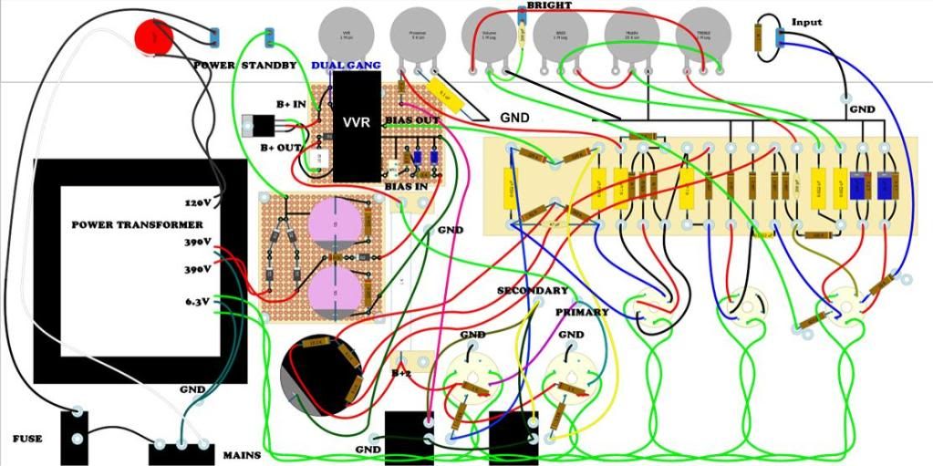
I have read a lot on Amp Garage and elsewhere on the net that the Express is a tough nut to crack and that it's sensitive to lead dress. While I think the Trainwreck amps are some of the classiest looking amps out there I didn't really want to build mine the same way. I decided to make a new layout more like a Marshall or Fender. I decided to use a JJ multicap (500V 40-20-20-20) after the VVR.
Here is my layout done in DIY Layout Creator. I blacked out the fixed bias VVR. You can order a VVR from Dana Hall.
[IMG 511]http://i291.photobucket.com/albums/ll31 ... yout-1.jpg[/img]
I didn't follow my layout dead on, but it was a guide to help me as I built the amp. I started with a grid stopper of 15k on V1a and 820 on V1b. I removed the input grid stopper. I have no oscillation or RF but with a true bypass tuner and volume cranked there is some RF on the input so I might put a small stopper on the input (I don't want to kill the ability to clean up with the guitar volume, which is awesome). Maybe I should use a small RF cap on the input.
I wound up needing a larger grid stopper on V1b. I had nasty blocking distortion or some oscillation. There was no oscillation without signal. After I cranked the volume above about half I could play full on no problem but notes would glitch or distort while sustaining. I put a big 82k grid stopper to kill the problem. Now I need to use progressively smaller stoppers to see how low I can get away with.
In tracking down the blocking distortion, I pulled V1, shorted V1a grid to V2 grid and ran an op-amp boost with really high gain (my own design) into the input. This sounded phenomenal! Enough to convince me to make an amp like this, haha. No preamp controls were active and it sounded great. The op-amp boost is very transparent.
I used stranded (not braided) shielded wire from volume to V1b grid. Maybe I wouldn't need the grid stopper if I used some foil shielded wire?
I was away for a couple of weeks so I was trying to track down the blocking in SPICE. In the stock Trainwreck, with a 12AX7 model that includes grid conduction, there seems to be a fair amount of grid conduction on V2.
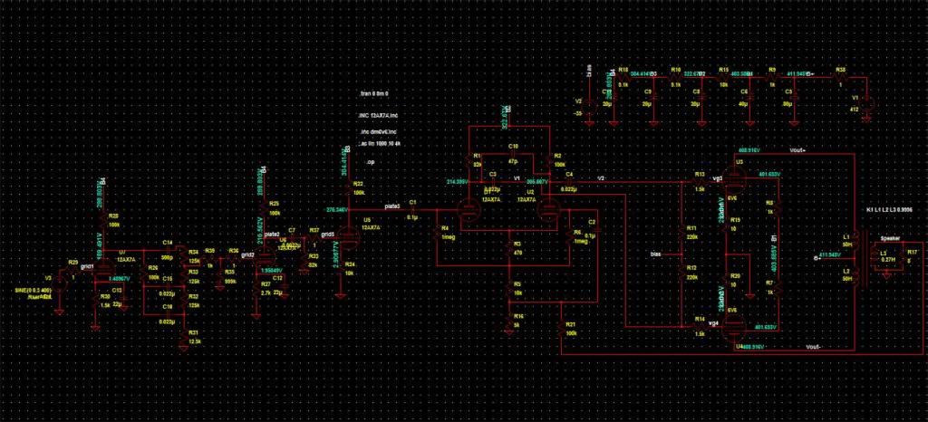
Here is the full SPICE schematic:
[IMG466]http://i291.photobucket.com/albums/ll31 ... atic-1.jpg[/img]
And the grid conduction:
[IMG466]http://i291.photobucket.com/albums/ll31 ... uction.jpg[/img]
Decreasing the 0.0022uF cap to 0.001uF or the 100k down to around 27k really seems to kill this grid conduction. There are a few variants in that .pdf and I know some have 0.001uF and 56k, etc... I used 0.0022uF and 82k. The first thing I changed in my build was the 82k down to 27k. This didn't help my blocking or whatever was going on as it was at V1b that I needed the grid stopper. This resistor really changes the "craziness" of the amp and I will be trying it back up at 100k now. Here is the effect of changing down to 27k:
[IMG466]http://i291.photobucket.com/albums/ll31 ... on_27k.jpg[/img]
^ There is something funky going on with the modeling there (beyond the scope of my interest ).
).
Here is my layout done in DIY Layout Creator. I blacked out the fixed bias VVR. You can order a VVR from Dana Hall.
[IMG
 511]http://i291.photobucket.com/albums/ll31 ... yout-1.jpg[/img]
I didn't follow my layout dead on, but it was a guide to help me as I built the amp. I started with a grid stopper of 15k on V1a and 820 on V1b. I removed the input grid stopper. I have no oscillation or RF but with a true bypass tuner and volume cranked there is some RF on the input so I might put a small stopper on the input (I don't want to kill the ability to clean up with the guitar volume, which is awesome). Maybe I should use a small RF cap on the input.
I wound up needing a larger grid stopper on V1b. I had nasty blocking distortion or some oscillation. There was no oscillation without signal. After I cranked the volume above about half I could play full on no problem but notes would glitch or distort while sustaining. I put a big 82k grid stopper to kill the problem. Now I need to use progressively smaller stoppers to see how low I can get away with.
In tracking down the blocking distortion, I pulled V1, shorted V1a grid to V2 grid and ran an op-amp boost with really high gain (my own design) into the input. This sounded phenomenal! Enough to convince me to make an amp like this, haha. No preamp controls were active and it sounded great. The op-amp boost is very transparent.
I used stranded (not braided) shielded wire from volume to V1b grid. Maybe I wouldn't need the grid stopper if I used some foil shielded wire?
I was away for a couple of weeks so I was trying to track down the blocking in SPICE. In the stock Trainwreck, with a 12AX7 model that includes grid conduction, there seems to be a fair amount of grid conduction on V2.
Here is the full SPICE schematic:
[IMG
466]http://i291.photobucket.com/albums/ll31 ... atic-1.jpg[/img]And the grid conduction:
[IMG
466]http://i291.photobucket.com/albums/ll31 ... uction.jpg[/img]Decreasing the 0.0022uF cap to 0.001uF or the 100k down to around 27k really seems to kill this grid conduction. There are a few variants in that .pdf and I know some have 0.001uF and 56k, etc... I used 0.0022uF and 82k. The first thing I changed in my build was the 82k down to 27k. This didn't help my blocking or whatever was going on as it was at V1b that I needed the grid stopper. This resistor really changes the "craziness" of the amp and I will be trying it back up at 100k now. Here is the effect of changing down to 27k:
[IMG
466]http://i291.photobucket.com/albums/ll31 ... on_27k.jpg[/img]^ There is something funky going on with the modeling there (beyond the scope of my interest
-
ForcedFire
- Posts: 34
- Joined: Sat Mar 05, 2011 4:35 pm
Re: Express build, new layout: The 6V6 Brainwrecker!
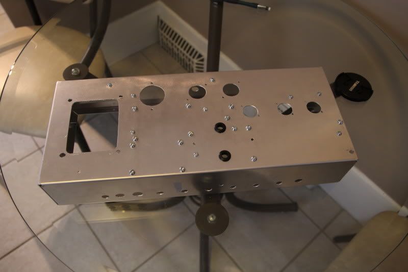
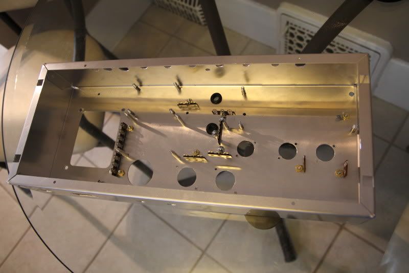
I chose my chassis based on being able to hand cut it, and what Newark had... It is a BUD chassis 17" x 7" x 3" 50mil.
My hand cutting and some hardware installed:
[IMG:800:533]http://i291.photobucket.com/albums/ll31 ... 0002_1.jpg[/img]
[IMG:800:533]http://i291.photobucket.com/albums/ll31 ... 0004_1.jpg[/img]
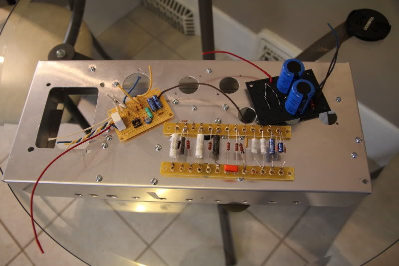
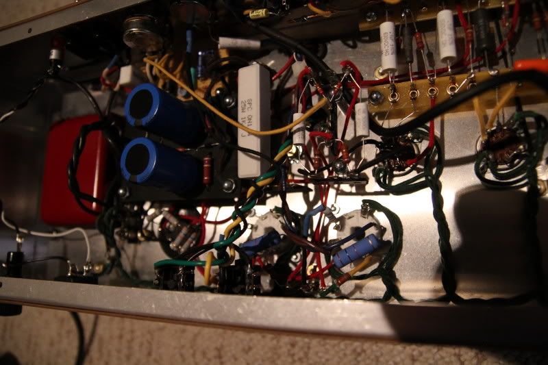
The rectifier and first filter caps, VVR / bias board, Preamp (AES strips):
[IMG:800:533]http://i291.photobucket.com/albums/ll31 ... 0001_1.jpg[/img]
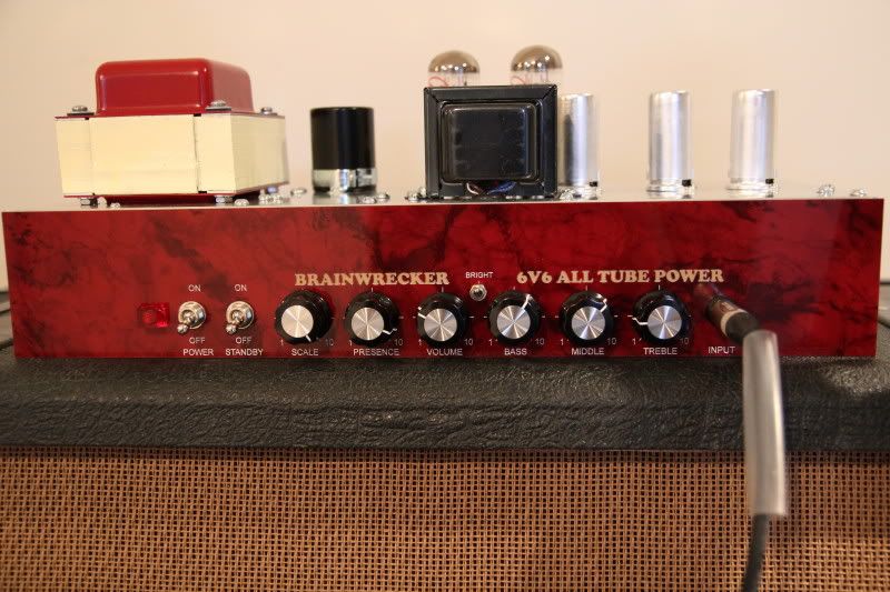
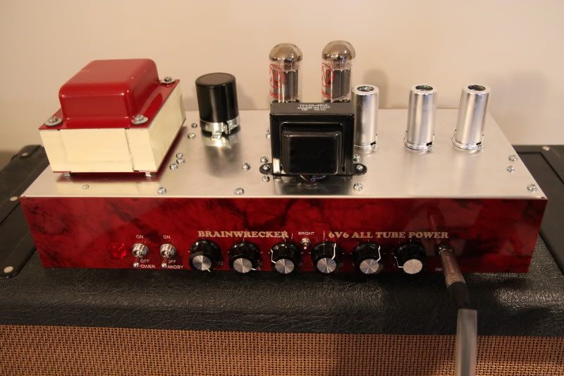
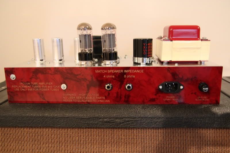
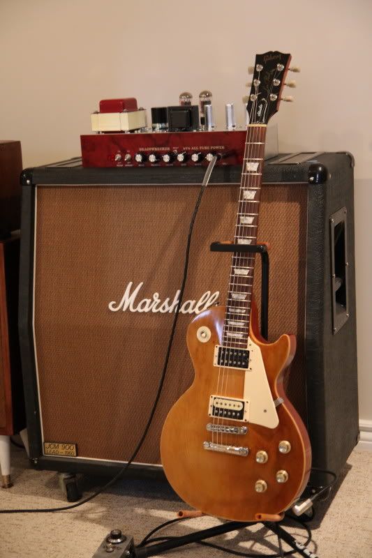
All finished! The panel had to fit in a 12" x 2" cut out in an empty headshell I had. The faceplates are laser engraved by Waterloo Engraving (~$23 each plus shipping). The gold lettering didn't have enough contrast on the front so I squeegee'd some white paint into the lettering:
[IMG:800:533]http://i291.photobucket.com/albums/ll31 ... r_0002.jpg[/img]
[IMG:800:533]http://i291.photobucket.com/albums/ll31 ... r_0003.jpg[/img]
[IMG:800:533]http://i291.photobucket.com/albums/ll31 ... r_0004.jpg[/img]
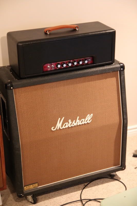
The head cab still needs piping, hardware, here's a preview:
[IMG:533:800]http://i291.photobucket.com/albums/ll31 ... r_0012.jpg[/img]
My hand cutting and some hardware installed:
[IMG:800:533]http://i291.photobucket.com/albums/ll31 ... 0002_1.jpg[/img]
[IMG:800:533]http://i291.photobucket.com/albums/ll31 ... 0004_1.jpg[/img]
The rectifier and first filter caps, VVR / bias board, Preamp (AES strips):
[IMG:800:533]http://i291.photobucket.com/albums/ll31 ... 0001_1.jpg[/img]
All finished! The panel had to fit in a 12" x 2" cut out in an empty headshell I had. The faceplates are laser engraved by Waterloo Engraving (~$23 each plus shipping). The gold lettering didn't have enough contrast on the front so I squeegee'd some white paint into the lettering:
[IMG:800:533]http://i291.photobucket.com/albums/ll31 ... r_0002.jpg[/img]
[IMG:800:533]http://i291.photobucket.com/albums/ll31 ... r_0003.jpg[/img]
[IMG:800:533]http://i291.photobucket.com/albums/ll31 ... r_0004.jpg[/img]
The head cab still needs piping, hardware, here's a preview:
[IMG:533:800]http://i291.photobucket.com/albums/ll31 ... r_0012.jpg[/img]
-
ForcedFire
- Posts: 34
- Joined: Sat Mar 05, 2011 4:35 pm
Re: Express build, new layout: The 6V6 Brainwrecker!
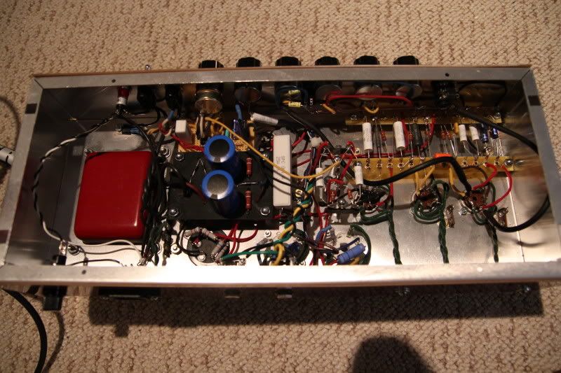
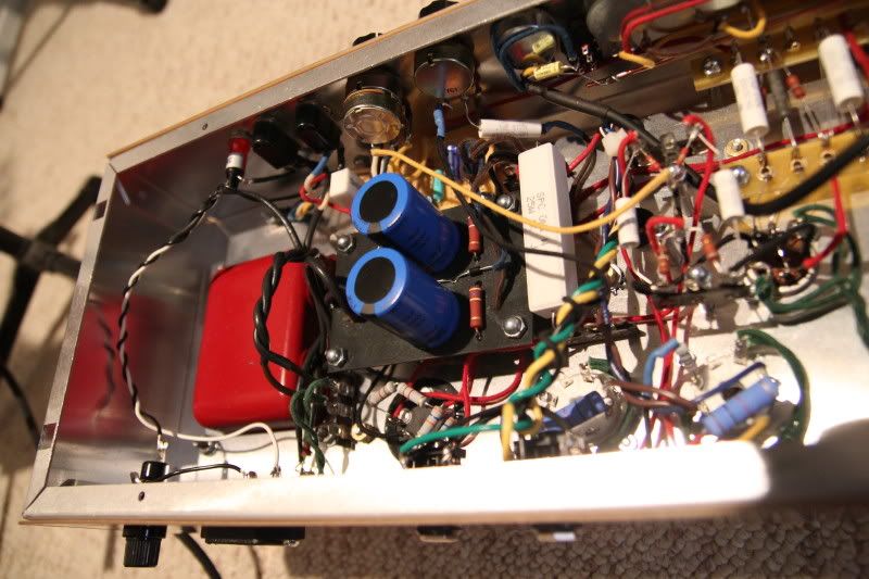
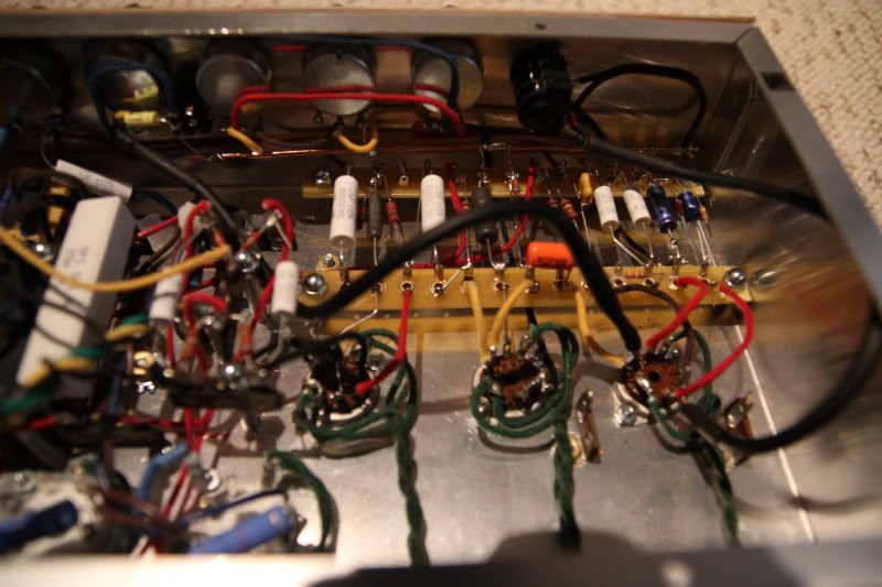
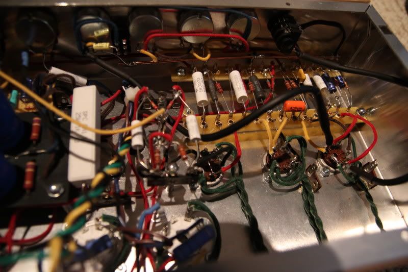
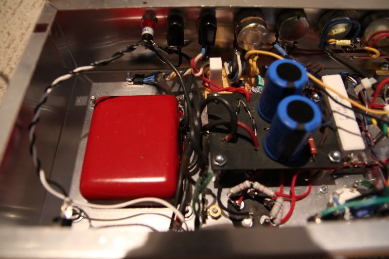
The guts:
[IMG:800:533]http://i291.photobucket.com/albums/ll31 ... r_0006.jpg[/img]
[IMG:800:533]http://i291.photobucket.com/albums/ll31 ... r_0008.jpg[/img]
[IMG:800:533]http://i291.photobucket.com/albums/ll31 ... r_0009.jpg[/img]
[IMG:800:533]http://i291.photobucket.com/albums/ll31 ... r_0010.jpg[/img]
[IMG:800:533]http://i291.photobucket.com/albums/ll31 ... r_0011.jpg[/img]
The VVR:
[IMG:800:533]http://i291.photobucket.com/albums/ll31 ... r_0007.jpg[/img]
Unfortunately I will need a heatsink, or limit the amount of voltage I try to drop from the VVR. With the scale down to about 5 on the dial, the chassis is getting pretty hot. I am using a mica insulator with heat paste. The chassis is just too thin.
From wikipedia, the maximum wattage a MOSFET with heatsink can handle:
Qmax = (Tjunction_max-Tambient)/(Rjunction_case+Rinsulator+Rheatsink)
Assuming 56mA draw and B+ minimum of 120V, I'm dropping 392V or trying to burn off 22W in the MOSFET. I will have to limit the minimum B+, I don't want to add grid capacitors ( have to limit the whole amp due to high B+ from PT).
So:
Qmax = 22W
Tjunction_max = 150 C (datasheet)
Tambient = 70 C (assumed)
Rjunction_case = 0.78 C/W (datasheet)
Rinsulator = 0.1 C/W (assumed)
Rheatsink = x (unknown)
22*(0.88+x) = 80
x = 2.76
So I need a heatsink with 2.76 C/W just for the idle consumption. Hopefully mounting a big heatsink in the side of the chassis will be enough to handle the current under full signal.
I think I was happier with the sound before dropping the V2 grid leak. This amp is very high gain but it doesn't seem so loud when I have it cranked. I can't hear anything after so it must be loud but it's kind of a sweet sound and not punishing or ear piercing. When I turn up the volume to about 1 it's VERY loud and bright. As it's turned up it gets that amazing harmonic feedback going on. So cool. I think it's the effect of the negative feedback that makes it less brain piercing compared to my 18W. That thing sounds loud like someone is stabbing me in the head, in a good way of course.
I might try a stopper on V2 as well and seeing as though there is an unsed triode, it wouldn't be beyond me to try a cathode follower before the 3rd gain stage!
I really need to play with the V2 grid leak and V1 stoppers, as well as the heatsink setup vs just limiting the minimum B+ to a higher voltage. Any suggestions are welcome!
Thanks for reading!
[IMG:533:800]http://i291.photobucket.com/albums/ll31 ... r_0001.jpg[/img]
Nathan
-
tele caster
- Posts: 189
- Joined: Sat May 24, 2008 5:17 pm
Re: Express build, new layout: The 6V6 Brainwrecker!
Nice work, thanks for posting such detailed build pics.
Re: Express build, new layout: The 6V6 Brainwrecker!
I made a amp out of a M3 organ amp as well.
I ended up with a Rocket of sorts.
What kind of B+ are you getting on your plates?
I had to use a 25v Zener to bring down the B+ low enough.
BTW, those power transformers have aluminum end bells and they polish up nicely.
The flux band on them is copper and once you clean the silver paint off they look real nice.
But the paint job looks sharp as well.
This picture sort of shows it but it's pretty shiny.
You do not have the required permissions to view the files attached to this post.
Tom
Don't let that smoke out!
Don't let that smoke out!

Re: Express build, new layout: The 6V6 Brainwrecker!
Wow, a lot of work there! From what you are reporting it definitely sounds like you are in the Express camp.
OK, suggestions? First off, change power tubes. Since you included the 6V6 name in your faceplate, this may be hard for you. J/J makes some nice power tubes, but try the KT77 or even their 6L6GC for something different in this amp. I prefer the KT77 here easily. As to the cathode follower prior to V3, NO! I tried it. It robs huge preamp power - surprising how much - and makes the amp become rather small and docile, everything it should not be I think. Smoothly distorted, yes, but ultimately boring and not an Express. It turns out that this section, the exit from V2, and particularily the gain stage just prior to it, is I think the 'heart' of the Express preamp circuit. You can lose weeks fine tuning this area, I know I did. Eh, but try the cathode follower idea if you must. Just don't forget what I said, and , when you switch it back to stock you maybe need to take a pic of your face as you play the amp.
  It was quite a surprise, like I said.
Any, whew, that's a lot of work - looks great - and I don't mean to be dissing it by any means. But do change those power tubes, you will have a better amp.
OK, suggestions? First off, change power tubes. Since you included the 6V6 name in your faceplate, this may be hard for you. J/J makes some nice power tubes, but try the KT77 or even their 6L6GC for something different in this amp. I prefer the KT77 here easily. As to the cathode follower prior to V3, NO!
Any, whew, that's a lot of work - looks great - and I don't mean to be dissing it by any means. But do change those power tubes, you will have a better amp.
Most people stall out when fixing a mistake that they've made. Why?
-
ForcedFire
- Posts: 34
- Joined: Sat Mar 05, 2011 4:35 pm
Re: Express build, new layout: The 6V6 Brainwrecker!
My problem is that these tubes will draw way too much plate current for my PT. The whole goal of this amp is to repurpose this PT. It can handle the Heater current I would think but apparently the high voltage winding is wimpy.rooster wrote:Wow, a lot of work there! From what you are reporting it definitely sounds like you are in the Express camp.
OK, suggestions? First off, change power tubes. Since you included the 6V6 name in your faceplate, this may be hard for you. J/J makes some nice power tubes, but try the KT77 or even their 6L6GC for something different in this amp. I prefer the KT77 here easily.
I know I could just buy a different one and make an Express with any power tubes but this one will have to be 6V6. I haven't tried NOS 6V6 yet. I have some but will have to try to match them or buy a pair.
I haven't seen voltage readings for a 'real' express clone running 6V6. I'm assuming the B+ is a little higher than with EL34. I might want to try lowering the preamp voltages so they match that of the EL34 express.
OK, this is a BIG helprooster wrote: As to the cathode follower prior to V3, NO!